Coding delimer

It is impossible to assess that code without knowing how the Neopixel string is laid out in its frame. That layout defines the mapping that is needed.

If you can describe what you expected to see and what actually happened then that might give you a clue to what the layout is. However it would be much easier to figure the layout from an example if you use an image that is simpler than text.

The LEDs are in serpentine or zig-zag layout. That code determines which linear pixels to use from Column/Row coordinates.

Jeff,
The layout is serpentine or zig-zag starting with pixel 0 (0,0) in the top right. The arrangement is by row. That is the first row from right to left is 0-24, the next is left to right 25-49 and so on.

1 Like

OK. Then I would recommend using the code you have in a small test program that lights the LEDS in simple patterns, one after the other, calculated from row/column. For instance, all row1, all row 2, all column 1, diagonal, reverse diagonal. That will tell you whether or not the code you have is calculating Neopixel number from row/column numbers correctly. If it is correct then you can work backwards to see why you aren’t getting what you expect from the buffer. If it is wrong then you can juggle the calculation until it comes out right.

1 Like

Just for the fun of it, I run a quick test with your i = code

if r % 2 == 0:
   i = (r * COLS) + (COLS - 1) - c
else:
   i = (r * COLS) + c

the mapping I got (i values plotted)

Note sure if your first pixel is on the right or left, but that code would make it on the right (assuming 0 base arrays and c = 0 to cols-1

1 Like

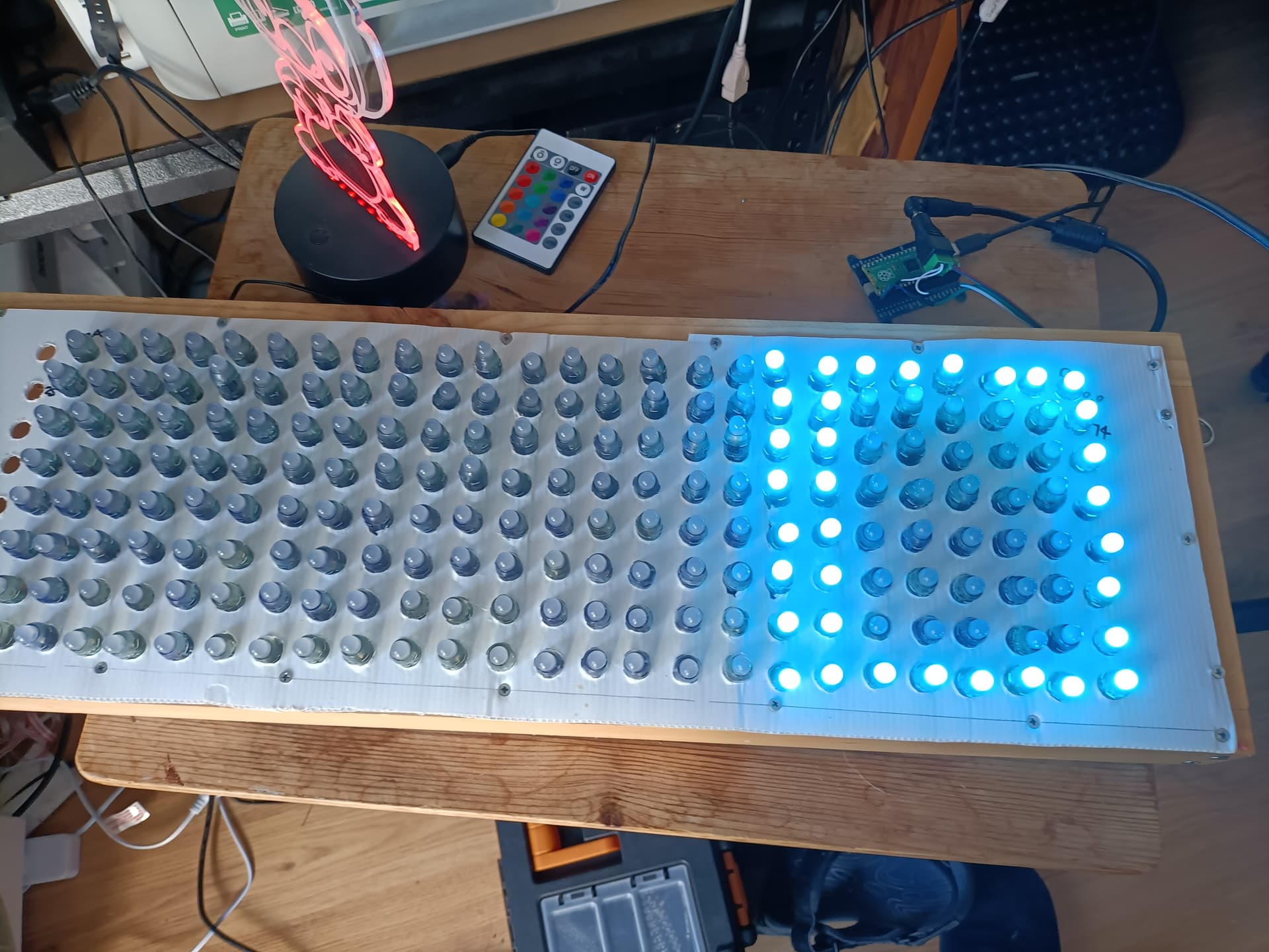
Michael that seems to be mostly correct. Though the matrix is 25 columns by 8 rows. Pixel 0 is indeed in the top right position. As suggested by Jeff105671 I have run test to confirm that the linear pixel is being correctly calculated. The code seems to be correctly calculating the linear pixel. Here is the update code.
You can ignore the block commented code. I also added a function to calculate the linear pixel from row/column coordinates.

import machine, neopixel, time, random, sys, os
import framebuf, struct

ROWS = 8
COLS = 25
LED_PIN = 16
FRAMEBUF = COLS * ROWS
pattern = bytearray(8)
pattern[0] = 0xFF
pattern[1] = 0x81
pattern[2] = 0x81
pattern[3] = 0x81
pattern[4] = 0x81
pattern[5] = 0x81
pattern[6] = 0x81
pattern[7] = 0xFF
def rgbto(r,g,b):
    v = (g << 16) + (r << 8) + b
    
    return(v)

def rgbfrom(v):
    b = v & 255
    g = (v >> 8) & 255
    r = (v >> 16) & 255
    
    #print("V={} R={} G={} B={}".format(v,r,g,b))
    
    return (r,g,b)

# Calculate linear pixel from Column/Row coordinates
def linearPixel(row,col):
    #Determine if row is odd or even
    #Right to left pattern 0 to 24
    if row % 2 == 0:
        i = (row * COLS) + col
    else:
        i = (row * COLS) + (COLS - 1) - col
    #Left to right pattern 24 to 0
    """
    if r % 2 == 0:
        i = (r * COLS) + (COLS - 1) - c
    else:
        i = (r * COLS) + c
    """
    return(i)
try:
    msg = "Micropython Rules!"
    np = neopixel.NeoPixel(machine.Pin(LED_PIN), COLS*ROWS, bpp=3)
    """ Comment out framebuf code while performing simple Neopixel patter tests
    print(id(np))
    FRAMEBUF = len(msg) * ROWS * 8
    fbuf = framebuf.FrameBuffer(bytearray(FRAMEBUF), COLS, ROWS, framebuf.MONO_VLSB)
    fbuf.fill(0x00)
    #fbuf.hline(0,1,COLS,0x01)
    #fbuf.line(1,0,COLS,1,rgbto(0,255,0))
    fbuf.text(msg,0,0,0x01)
    i = 0
    m = 0
    """
    """
    for r in range(ROWS):
        for c in range(len(msg)*8):
            if fbuf.pixel(r,c) != 0:
                l = l + "*"
            else:
                l = l + " "
        print(l)
        l = ""
    """        
    """
    while m <= FRAMEBUF:
        for c in range(COLS-1,0,-1):
            for r in range(0,ROWS):
                rgb = fbuf.pixel(m,r)
                #print("C={} R={} RGB={} Pixel={}".format(c,r,rgb,fbuf.pixel(c,r)))
                if r % 2 == 0:
                    i = (r * COLS) + (COLS - 1) - c
                else:
                    i = (r * COLS) + c
                if rgb != 0:
                    np[i] = (255,0,0)
                else:
                    np[i] = (0,0,0)
                print("I={0} C={1} R={2} FRAMEBUF={3} M={4}".format(i,c,r,FRAMEBUF,m))

            np.write()
            time.sleep(.1)
            m += 1
            #fbuf.scroll(-1,0)
    """
    # Simple line test Row 0
    for c in range(COLS):
        i = linearPixel(0,c)
        np[i] = (255,0,0)
        np.write()
        time.sleep(.1)
    # Simple line test Row 1
    for c in range(COLS):
        i = linearPixel(1,c)
        np[i] = (0,0,255)
        np.write()
        time.sleep(.1)
    # Simple column test Column 1(2)
    np.fill((0,0,0))
    for r in range(ROWS):
        i = linearPixel(r,1)
        np[i] = (128,0,255)
        np.write()
        time.sleep(.1)    
    # Simple diaginal line test start at 0,0
    np.fill((0,0,0))
    c = 0
    for r in range(ROWS):
        i = linearPixel(r,c)
        np[i] = (0,255,0)
        np.write()
        time.sleep(.1)
        c += 1
    # Simple reverse diaginal line test start at 7,7
    c = 7
    for r in range(ROWS-1,-1,-1):
        i = linearPixel(r,c)
        np[i] = (0,255,128)
        np.write()
        time.sleep(.1)
        c -= 1
    # Make a cross
    c = 0
    for r in range(ROWS-1,-1,-1):
        i = linearPixel(r,c)
        np[i] = (0,255,128)
        np.write()
        time.sleep(.1)
        c += 1
    # Display simple box pattern from bitmap
    for r in range(ROWS):
        bt = 1
        for c in range(ROWS):
            i = linearPixel(r,c)
            #print(f'pattern[{r}]={pattern[r]:#010b} bit[{c}]={pattern[r]&bt} {bt}')
            if pattern[r]&bt != 0:
                np[i] = (128,0,128)
            else:
                np[i] = (0,0,0)
            bt = bt << 1
        np.write()
        time.sleep(.1)
    # Move simple box pattern from bitmap one column to the left (scrolling)
    np.fill((0,0,0))
    for p in range(COLS):
        for r in range(ROWS):
            bt = 1
            for c in range(p):
                i = linearPixel(r,c)
                print(f'pattern[{r}]={pattern[r]:#010b} bit[{c}]={pattern[r]&bt} {bt}')
                if pattern[r]&bt != 0:
                    np[i] = (0,0,128)
                else:
                    np[i] = (0,0,0)
                if bt <= 128:
                    bt = bt << 1
                else:
                    bt = 1
            np.write()
            time.sleep(.1)
    time.sleep(3)
except KeyboardInterrupt as e:
    sys.print_exception(e)
    print("Exiting...")
except IndexError as e:
    sys.print_exception(e)
    print("4:Index out of range C={} R={} I={}".format(c,r,i))
except (Exception, NameError, RuntimeError) as e:
    sys.print_exception(e)
    print(f"Unexpected {e=}, {type(e)=}")
finally:    
    np.fill((0,0,0))
    np.write()
1 Like

Hi All,

It would also be worth having a look at how GlowBit works behind the scenes, there is some drawing of strings happening in there: https://core-electronics.com.au/guides/glowbit/glowbit-matrix-8x8-python-and-micropython-guide/

1 Like

Liam,
Are suggesting the Glowbit library will work with WS2812 RGB LEDS? I have a 8*8 Globit matrix from what I can see there doesn’t appear to any electronics to translate the x/y coordinates.

Did your test for the top row (for example) actually fill the display from right to left? That’s what I get from the description of the string layout and the code you are using. Since the code you are going to use to display the characters will assume that column 0 is on the left, then the linear pixel is not being correctly calculated.

the numbers you want to see for the top two rows are

c 0 1 2 3 4 5 6 7    8 9 10 11 12 13 14 15
i 7 6 5 4 3 2 1 0    8 9 10 11 12 13 14 15

You need to swap the tests for r to get the Leds lighting from left to right for the rows that are actually running from right to left.

1 Like

Jeff,
Are taking c & i from my code? If that is so c = column and i = linear pixel. In both cases position 0,0 and linear 0 are top right. The patter being right to left even rows 0-24, 50-74 etc. Odd rows left to right 25-49, 75-99 etc. If look at the latest code posting that will hopefully show what I mean. I followed you suggestion and tested the row/column coordinates to linear pixel. All the tests except the scroll test worked as expected.
The scroll test did not scroll the pattern it displayed multiple patterns.

Unless I am understanding something incorrectly then that’s not right. I would expect that (0,0) should be top left, which would be linear 7. The buffer will be laid out left to right, top to bottom. You can correct for the layout difference either in accessing the buffer or in calculating i, but you have a calculation for i that allows for a serpentine pattern (albeit one starting at top left) so I assume you want to do the mapping in the i calculation.

You might be able to resolve this by making clear what you are expecting to see on the display and what you are actually seeing, as mentioned above. That’s always the best way to sort out what might be happening. Also, use a simpler and much smaller character pattern than the message you have chosen, and don’t try to scroll until you have the display correct.

1 Like

Thank you for all the advice. I will attach some photos of the matrix.


1 Like

I do have a short video showing some tests. However it exceeds the allowable file size. It is compressed.

If you have a small enough example (such as a single character with no scroll) then a description is adequate and a video is not required.

Can you explain why you have marked LED 0 as coordinate (0,0)? That would indicate that the matrix is 8x25 with a serpentine layout starting at top left, which you have stated is not the layout. If it’s 25x8 with a serpentine layout starting at top right (which is what the image of the wiring indicates) then Led 0 must be coordinate (24,0).

Jeff,
The layout is serpentine(or zig zig) with top right being the start of the string.

#Code segments
#Pattern definition
pattern = bytearray(8)
pattern[0] = 0xFF
pattern[1] = 0xC1
pattern[2] = 0xC1
pattern[3] = 0xC1
pattern[4] = 0xC1
pattern[5] = 0xC1
pattern[6] = 0xC1
pattern[7] = 0xFF
    # Display simple box pattern from bitmap using above pattern
    for r in range(ROWS):
        bt = 1
        for c in range(ROWS):
            i = linearPixel(r,c)
            #print(f'pattern[{r}]={pattern[r]:#010b} bit[{c}]={pattern[r]&bt} {bt}')
            if pattern[r]&bt != 0:
                np[i] = (128,0,128)
            else:
                np[i] = (0,0,0)
            bt = bt << 1
        np.write()
        time.sleep(.1)
	# This code displays bits 0 & 1 to the left of the matrix the columns 7 & 6.

> Can you explain why you have marked LED 0 as coordinate (0,0)? That would indicate that the matrix is 8x25 with a serpentine layout starting at top left, which you have stated is not the layout. If it’s 25x8 with a serpentine layout starting at top right (which is what the image of the wiring indicates) then Led 0 must be coordinate (24,0).
LED 0 is at coordinate 0,0. LED 24 is at 0,24. As per the code below

    # Simple line test Row 1
    for c in range(COLS):
        i = linearPixel(1,c)
        np[i] = (0,0,255)
        np.write()
        time.sleep(.1)
    # Simple column test Column 1(2)
    np.fill((0,0,0))
    for r in range(ROWS):
        i = linearPixel(r,1)
        np[i] = (128,0,255)
        np.write()
        time.sleep(.1)    

Check these photos. One is for lines, the other is the pattern(character).


1 Like

Only if your coordinate system starts at top right and proceeds to the left and down. But that isn’t how the buffer is laid out, and it’s not how the display is laid out. Mapping pixels from the buffer to the matrix means mapping from a coordinate system in the buffer that starts at the top left and proceeds to the right. That coordinate system has to be mapped to a string that starts at the top right then runs left then right then left etc down the rows.

So if you want to light the LED at the top left position in the matrix (0,0) you must light the 25th LED from the start of the string at the top right, ie LED number 24.
Serpentine

Hi All
Digressing quite a bit here but I have been wondering about the title of this thread, in particular regarding the word “Delimer”
When running a query this comes up as a descaling product, usually liquid for removing lime scale etc. What that has to do with this problem escapes me.

Maybe the correct term would be “Dilemma” as in “What do I do??”
Probably just a spelling error but it has been bugging me since it was first posted.
Cheers Bob

Jeff,
I have changed the linearPixel algorithm to treat LED 24 as 0,0. As per

# Calculate linear pixel from Column/Row coordinates
def linearPixel(row,col):
    #Determine if row is odd or even
    #Left to right pattern 24 to 0
    if row % 2 == 0:
        i = (row * COLS) + (COLS - 1) - col
    else:
        i = (row * COLS) + col
    return(i)

Robert,
Spelling isn’t a strong point of mine.

Hi Adrian

Forgiven. You are not alone. The English language has some funny spellings at the best of times.
Cheers Bob

Good. What was the result with a simple character?

1 Like