Just going back to basics. If you are driving into an unknown load which could be a short, then outputting a high will fry the output. Not immediately, my experience is if you realise the mistake within seconds you may get away with it. So to be safe put a resistor on each output. The specs say can source/sink 7ma at around 3V so 470 ohm would be OK. That is quite a small resistance in a logic path so it should not interfere with signalling. After reading the whole post I still have no idea what is to be achieved. If it is to detect a patch between two pins you’d have to scan - 1 output and check all the others as inputs. Move to the next pin as output and check the remainder as inputs, until you are looking at the last two pins. Outputting two outputs at once will be hard to decode I think.
Those triangle symbols are not really op-amps, they are used in high level schematics to indicate a driver or buffer of some sort. They protect the micro along with the clamping resistors from transients and voltage spikes.
AND the post by @Michael99645 was of the internals of the Raspberry Pi for each GPIO port.
The patch panel pic is for audio. In my work we used patch panels to connect and disconnect data communications paths. If I remember right the patch panel was for RS232 or RS422 data. It had also had a monitor port which we used to check circuits that had been reported as faulty. All patch panels we used were passive, they just linked wires together, essentially a breakout point.
With your idea of connecting GPIO to GPIO; if the patch distance was not great you could connect directly, or if worried about transients use a buffer IC.
Cheers
Jim
You would have to know beforehand which direction. ie; Is a particular GPIO Input or Output.
Or dedicate GPIOs as in or out and work around that.
You could always insert a buffer into the patch cable but that makes them directional and still has to be powered. Another scenario would be little boxes with a buffer inside. fitted with a male and female connector so could be inserted into the patch panel as required. This would also have to be powered but this would be easier done than powering a cable.
Gets a bit messy.
Cheers Bob
If you think of the panel as a matrix with outputs as columns and inputs as the rows, then any element that is a ‘1’ is a connection and will pass your ‘data’ through.
In python a matrix is a ‘list of lists’.
So think like this: each list is a representation where each position relates to a column.
general list definition [ out_a, out_b, out_c]
input_1_list[0,0,1] would mean input 1 connects to output c
input_2_list[1,0,1] would mean input 2 connects to outputs a and c.
then you are not building a hardware switch, but emulating it in software.
Dave
Hi everyone.
Just updating the thread with the solution I came up with.
Design 1
I first tried my original plan of 6 GPIOs in a grid such that:
- one and only one was in output
- the single output was always high
- all other GPIOs were listening as inputs (pulldown)
- any input that read high must be connected to that output
- record the links as tuples
- GPIOs take turns at being outputs.
Good news, that works.
However, I don’t recommend it because it relies on the code running on the pi being correct to avoid multiple outputs connecting to each other. It was also hard to reason about and debug.
Also I eventually want to scale this up where the cabling and code will just be too silly.
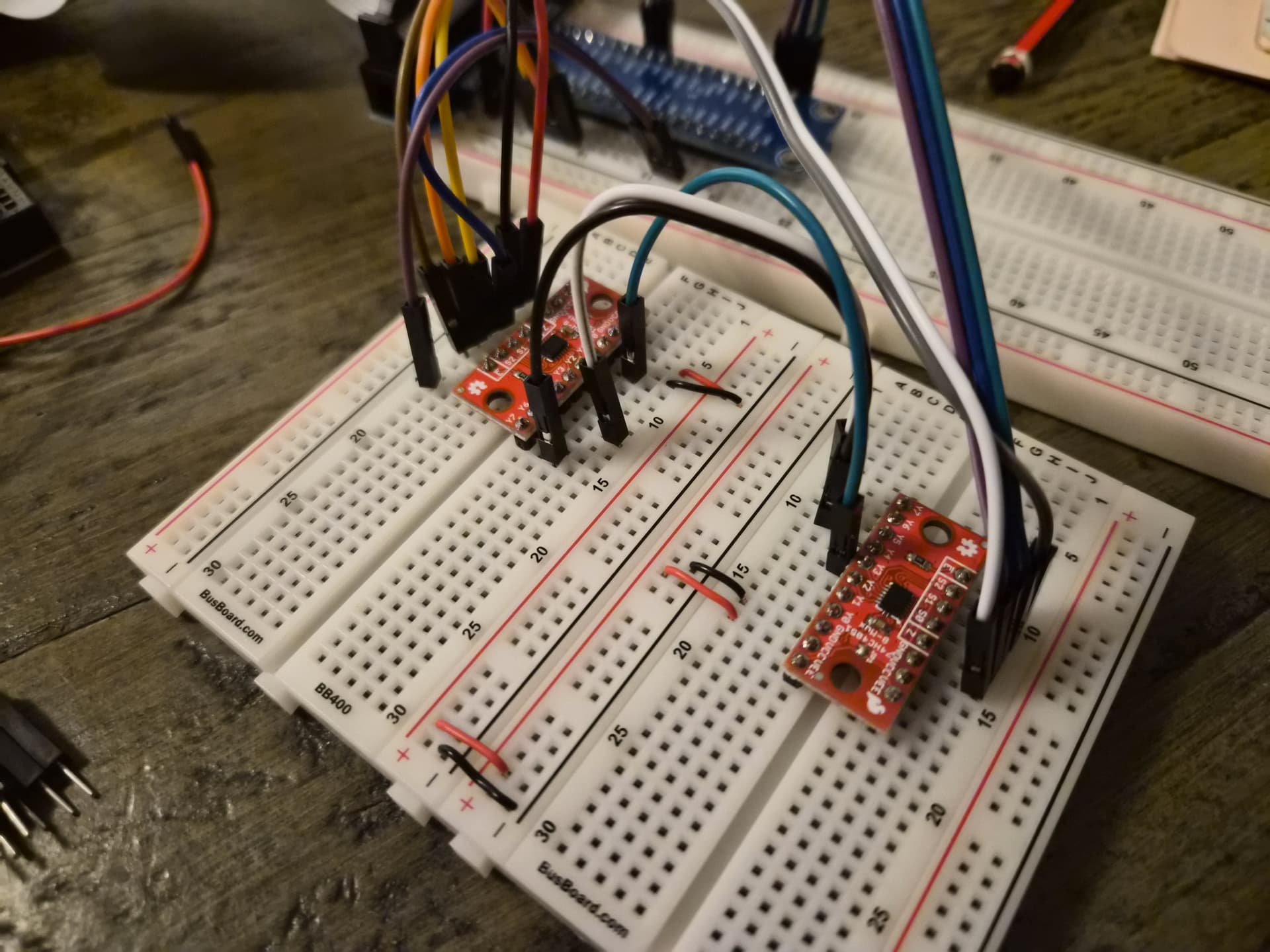
Design 2
In the end I settled on another design I was working on in parallel.
Here I’m using multiplexers. Similar idea, but now there is one fixed output and one fixed input.
Instead of changing GPIOs we’re just changing the index of the multiplexer.
More scalable; easier to think about. Unfortunately it requires some external hardware but I think that’s a fair trade for the simplicity. It has a few other advantages. Two programs or functions need not to be synchronized, the only condition is that the input mux needs to be at minimum 2 ^ #bits / 8 times faster than the output. Also, it’s easy to give dedicated IO to different listeners by locking them on unique indexes.
Hi Pix
Design 2.
Congratulations, what a great solution. A hardware approach would get pretty messy as GPIOs can be input or output.
Now you are talking my language. The key word being simplicity. Can’t beat it.
Cheers Bob