I’m trying to use the TPL5110 with a FeatherS2 (Unexpected Maker) but I can’t get it to work. I have it wired up the exact same way as the guide and I have the DONE pin connected to A5 on the feather. The board keeps shutting off the power before my code runs. The only thing I have noticed is that when the feather boots up, 0.35V is measured across the A5 pin and the power gets cut soon after which I’m assuming is the problem.
Using CircuitPython and this is my code to send a signal to the power board:
pin = digitalio.DigitalInOut(board.A5)
pin.direction = digitalio.Direction.OUTPUT
pin.value = False
…code…
pin.value = True
Hi all,
I though I share this, as I took me a while to figure it out. I am using a ESP32 DEVKIT V1 and the power was shutting down when the pin DNE was high, but never start again.
It’s due to the ESP32 putting all the PIN High for a short period of time at start up. The problem is solved by adding a 1K resistor between DNE and IN- to pull down the pin.
Happy making everyone.
Glad to hear Sy’s solution worked! Thanks heaps for sharing!
For future readers if someone runs into a similar problem and the pull-up/down resistor is now introducing odd behavior in the microcontroller, its likely that the pin being used is a bootstrapping pin, check out the docs on the MCU you are using!
Hi wonderful people,
I am helping my daughter with a school project. We need to turn a small motor on for maybe 20 seconds or so, then off for a longer time, maybe 5 minutes, maybe 30 minutes. Then continually loop the same on-short, off-long cycle.
I’m not too experienced with electronics, will this timer suit my needs?
Any help would be appreciated.
Take care all,
Nathan
The TLP chip on this board will keep the output on until a signal is received on the DONE pin, or the original delay elapses again. I.e. if it’s off for 30mins it’ll be on for 30mins.
The simplest way I can think of doing this is with a motor driver and Pico, here’s a guide:
You can do it with a 555 timer and some supporting circuitry, but it can be fiddly to tune values to get the timing right, especially when you’re talking in the timescale of minutes where it’s hard to figure out what it’s doing.
Hi, cool device - interested in using this for a project, looking for about an 8 min time interval.
The python script for the custom resistor selection is handy, but I’m not sure that it’s quite right - 2 possible issues.
the code errors because the calculation for R is missing a “+”. R = 100*(-b+sqrt(… (that’s the easy one from the data sheet)
getting the same values with 169k Ohm resistor being in parallel or if the trace is cut. If custom resistor is what we’re looking for in table 3 of the TPL511 data sheet (page 14), it’s not calculating those values.
For example, 8 min should be 52k Ohm, but the script is giving me 143k with or without the 169k in parallel (i.e. 77.4k or 143k if the trace is cut). It’s not making sense to me. Or maybe table 3 is not the right place to look.
Is the Rtmp calc on line 55 right?
Can someone who knows how this script is meant to work, please take a look?
Hey @David173576 - thanks for raising the comment about the script syntax error. I’ve seen this before when we upgraded the website and some articles lost content out of their code blocks.
fixed
I’m unsure about issue # 2, but coming at this one from the empirical direction, we know Switch C and D are 5 and 20 minutes respectively so the resistor value you want will lie somewhere between the value used on those settings.
Have a go at just relying on the datasheet table and remove the parallel 169k resistor from the circuit. We included that resistor to guarantee that by default (all switches are open) there would be a valid time set. When the DIP switches are soldered onto the board they are all open, which means the out-of-box configuration would be invalid were it not for this 169k resistor.
Try going with what the table prescribes for 8 minutes (52.24k, or 88.7k // 127.0k), and removing the 169k parallel resistor.
It is comforting that 52.24k is between our santiy check values for C and D (25.5k and 57.6k)
Yep, I was going by the datasheet table vs the schematic for the timer. The schematic has, for switches 3 and 4, which appear to be C and D, resistors of 57.6k and 143k. Not 25.5k, which appears to be B. It’s this mismatch that led me to the question, and using the python script.
@David173576 you’re right! I goofed on that one I didn’t correlate the actual switch positions properly and didn’t actually account for the parallel resistor. Apologies for the confusion.
Let me try again. With gusto this time.
User-specified time from datasheet
Remember the 169k parallel resistor? It’s always in circuit by default
Switch C is for 5 minutes, 57.6k
57.6k // 169k = 42.96k → matches the 5 minutes resistance from the datasheet
So we’ve demonstrated the equivalent resistances that are built-into the board make sense.
At the end of the day, the timer is programmed using a single resistance.
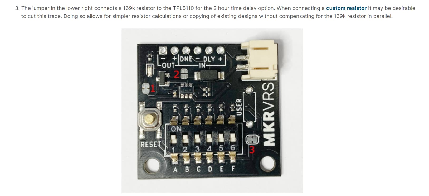
If you choose to use your own resistor, it may be simplest to remove the 169k resistance by soldering the jumper labelled 2 in this diagram
Then, you can use any exact value that you calculate, or take from the table of the datasheet.
The datasheet very kindly provides how to get near perfect resistances using the “Parallel of Two 1% Tolerance Resistors” column → for your eight minute interval you could use parallel resistors (88k7 and 127k)
Or you could get a multiturn pot and dial it in.
Testing the script
When I plug 8 minutes into the script it returns 52.3k Ohms for both scenarios (keeping, or removing the 169k parallel resistor)
That’s clearly a bug but it is at least correct for if we have shorted out the 169k resistance. I think the simplest way to proceed will be for this script to just always assume the 169k resistance is shorted-out.
How to proceed - The pursuit of the 8-minute timer
I think we got it!
short out the 169k resistance
connect a resistance of about 52.3k Ohms - either by combining series + parallel resistors or using a trimpot.
enjoy your 8 minute delay
accept the fact that it still won’t be 8.0000 minutes because of device tolerances
I hope this rather lengthy post clears things up for your (and others)
Let us know how you go!
Admittedly this code could have been commented a little better - but I think we’ve done a pretty good job in designing this product so that the table of values can just be used from the datasheet.
Thanks for your ‘several’ replies. I haven’t lost the plot, it all makes much more sense now. I had manually calculated 52.3k ohm but thought there must have been some other difference between the Makerverse circuit and the one in the TI data sheet. … and my copy of python script now works, bonus!
Anyway, I have the Nano timer HAT so I’ll be starting with that, without a user resistor, and if I run low on power with too much up-time, I’ll be back for this. At least now I am sure it will work for me if I need it!
Hi, sorry for the somewhat stupid question, I would like to be able to power a GPS tracker, which should fly for a few months with a super pressure balloon.
The tracker consumes approximately 150 mA during data transmission, which lasts approximately 4 seconds, and 70-90 mA when it is turned on but not transmitting. It takes about 1 minute to get GPS signal. I would like to power it using some 1.5V, 3000mAh AA Energizer batteries, but even using 10 of them, it would last less than a week.
I would like to increase the life by turning off the tracker, using the Nano power module, is this possible? I use a Vaisala rs41 radio probe, which is powered by two 1.5v AA batteries, if I can keep it on for at least a month it could go around the world. I tried to power it via solar panels, but it doesn’t turn on again because the voltage increases too gradually, I think the module can solve this problem too, but as a first attempt I will use batteries
Hi All
What sort of altitude are we talking about. RadioSonde balloons go up until they burst. How are you going to prevent the balloon just going up a hell of a long way.
What I am getting at is the GPS satellites where they operate a cone style pattern that illuminates overlapping bits of the Earth. Could this balloon keep going up until id gets out of the GPS satellites cones and the GPS will no longer function.
I know Aircraft can use the GPS system but maybe this balloon could go a lot higher than that. A manned balloon of course has someone to operate the air system and maintain altitude.
I don’t know if the Aircraft safety people would have anything to say about this venture would they???
Cheers Bob