Thanks for the kind comments.
Regarding using a microprocessor for timing, with a 1PPS input from a GPS module. I believe, but can’t find the reference again, that the time in NMEA messages applies to the next 1PPS, not the previous one.
It is very difficult to input and decode the NMEA messages while doing other things, so the best way (I found) was to read the time once at power up then update it internally on each 1PPS arrival. To get times down to less than a millisecond, rely on a free running timer in the uP. Almost all of them have 16 bit timers that run from 0 to 65535 then back to zero. And there’s usually a prescaler, dividing the uP clock so the timer is running slower if that is needed. By sampling the timer in an interrupt routine triggered by the 1PPS, it is possible to work out the actual uP clock speed, which may nominally be say 16MHz but could be a few percent low or high. Knowing the actual speed, it is possible to work out a fraction of a second just by dividing the number of timer ticks by the fraction. Given the timer sample captured by the 1PPS, and adding the fraction, gives a trigger time. Most uP allow setting a match value in a register that triggers an interrupt when the timer reaches that value, that can then be used to create an external event such as a camera click. It is easy then to trigger the event at a specific time within a millisecond or two, and repeat it at intervals as required (say 1000 frames at 1/10 second intervals starting at time x).
This is a somewhat simplified explanation, the crux being use a free running hardware timer as the basis for timing. Using programmed timed waits runs into complications because the code takes an unknown time to run and throws out the timing. Better to have the background task (the main program) running a continuous loop looking for events and setting up things to do, and allow the ISRs to create the events and do things at the time required.
Just adding a little here. If the NMEA packets can be tuned, then you can limit to the minimum to stop any unneeded UART RX IRQ to be processed.
And to refine my clock tuning approach; if needed, a simpler method could be
- On GPS Time Packet, set newtime = gps time + 1 second.
- On PPS set the clock to newtime
That should remove some code overhead in measuring tick differences.
I have been thinking this through, and conclude using any sort of GPS is unnecessary. It is almost essential there be a communications link that triggers cameras, as it is not possible to predict ahead of time when the cameras need to be triggered. A proposed setup is a controller linked to a transmitter, with camera(s) triggered by receivers. In practice it would be sensible to use microcontrollers for each. The receiver could be just a switch, but there are two desirable characteristics (1) the receiver does not false trigger (2) the receiver can verify it is receiving from the controller transmitter. This implies some logic in the receiver. The controller may need to be more complex. The receiver only needs to send a single “take a picture” command to the camera when the controller requests it, leaving all the logic of multiple shots, timing etc. to the controller.
A possible setup is to have the controller broadcast a test message every few seconds. Then move the camera and receiver to its location, the receiver having a LED that flashes as each test message is received. That verifies the receiver is … receiving. Once the cameras are positioned, then use the controller to send take a picture messages as desired.
It would be desirable for the receivers to have high gain directional antennae. This has the twin benefit of rejecting spurious signals from the wrong direction, and improving signals from the right direction. The antenna could be mounted on a pole to improve the line-of-sight situation. The controller has an omnidirectional antenna as it is broadcasting in all directions. Increasing power in a particular direction may run foul of the regulations.
Regarding simultaneous operation, radio waves travel 300m/microsecond so the distance from the transmitter is not an issue. If identical receivers and receiver logic is used, there should be no other issues apart from the camera itself. Cameras take time to evaluate light intensity, adjust focus, etc before making a shot. I have no expertise in the area but assume some research would be needed to determine how much delay (or more importantly, delay variation) can occur.
Yep, thats kinda where I got to; the key thing with this approach is simply any radio/comms overhead is both
a) the same - it should be if identical remote units
b) the camera “take a picture” time is the same - which it should be if all the cameras are the same.
Some of this project I think the OP is keen to use as a learning exercise to see the pros/cons of different things and just learn; as much as the final working picture sync.
I would expect basic lora would work within the specs as that is what it was designed to do. the lora transmitters/radios should have the option to ensure the channel is clear before transmitting; which is normally required for any radio/operator using the open bands.
Using the existing UHF 2 watt handheld units could be used as a trigger of tone/continues tone squelch is used, then you just need to monitor the “ear/speaker pin” to go “higher”; but a few other unknowns with the tx side. I am assuming the PTT is all that’s needed, and no second button to activate tone operations.
2 watt UHF should be more thing fine over 200-300 meters even if no line of site.
What I am getting at is given the short distance and existing radio gear or modules, we may not need anything special for the short distance; some field tests will be needed at some point.
Hi all
AHHH. The good old KISS principle is getting on top again
Regarding these UHF units. I would be a bit careful here. Sometimes the Powers That Be can get a bit stroppy when this sort of thing is modified to do a job it is not licensed for. Any mods you intend could be OK but there is a chance that ANY mods would be illegal. Just check before you do anything here.
Cheers Bob
While I fully agree and this needs to be from a better source.
" … * Channels 22 and 23 are allocated exclusively for telemetry and telecommand use or automated data communications…"
src: UHF Channels Australia | Handy Guide to CB Radio Channels
My idea was not to touch/modify the radio unit at all, rather use the accessory port, that has wires for “speaker/ear phone”, mic and ptt.
But yes, you are correct, need to be careful and find the actual rules for it.
Edit: The following seems to support the other site.
https://www.legislation.gov.au/F2015L00876/2017-04-08/text
Thanks so much guys. Thanks, Mike, for the testing you’ve done – I trust it’s all of interest to you.
You’re right in that I’m just as interested in the technical solution as in the end use. I definitely want a setup to operate a single camera remotely. We do birding and I’d love to get closeups of shore birds. Many birders use massive lenses, but gee they’re pricey. I’d like to place the camera device on a beach and retreat to a spot where I can spy on the birds. I’d trigger the camera when I think some are close and within shot.
I have a RC doorbell that only cost $10. It works well up to about 50m range. That could be modified to trigger a camera and I’ll probably try that out. But it wouldn’t do the job of triggering two cameras up to 200m. apart.
My GME radios: they are good quality; 2 watts gives us pretty good range, certainly good enough for this project. They have a PTT button which can also be set to voice activation. They can TX a short beep at release of the PTT to indicate to the RX party that you have ceased your talk. The beep could be used trigger a sound detection module. The radios have an earphone socket so I’ll try to see what voltages can be detected off that when I can access a scope in a week or so. I have some cheaper radios that could suffice a receivers, but not transmitters.
At the moment I’ll get my RPi zero W and its camera module going.
Don’t want the attention of the authorities so I think I should use the radios as supplied.
Hi John
Yes and they were actually made in Australia once. Not sure about now.
Just had a look at their web site. Apparently their products still are made locally. Strange!!!
Cheers Bob
OR you could issue a $PMTK255: PMTK_SET_SYNC_PPS_NMEA command to the module.
From Global Top, PMTK Packet User Manual, Revision: 1.2, Linked FW Version: AXN3.6/3.8/2.3/2.5, Release Date: 2016.05.30, which applies to this module (PA1616D with MTK3333)

This means that you can use the NEMA sentence to get timing accuracy between PPS and start of UART transmission down to 20ms, without using interrupts or using the PPS output. Depending on how it’s coded, add a couple more ms.
So in theory, can probably can get multiple units to fire withing 25ms just using the UART (I recommend 115,200 baud only). Using an interrupt generated from the PPS signal instead, I can’t see a reason why sub-microsecond timing isn’t possible, on an MCU module NOT running a RTOS (for me anyway, as I only use Python).
KISS? Well, just use a 200m long cable pair! ![]()
![]()
![]()
2 rolls of https://www.aliexpress.com/item/1005007060887939.html for $33
I kinda like this idea.
I’m definitely guilty of over-complicating very simple projects quite often.
Just a passing comment…
Even the simple solutions can end up having complicated issues.
e.g. OH&S, public liability/trip hazard etc
So yeah, run the cable, then flag it with the witches hats and signs. LOL
Hi everyone.
I haven’t given up on this project. Been exploring RC control of a DSLR and also ESP boards.
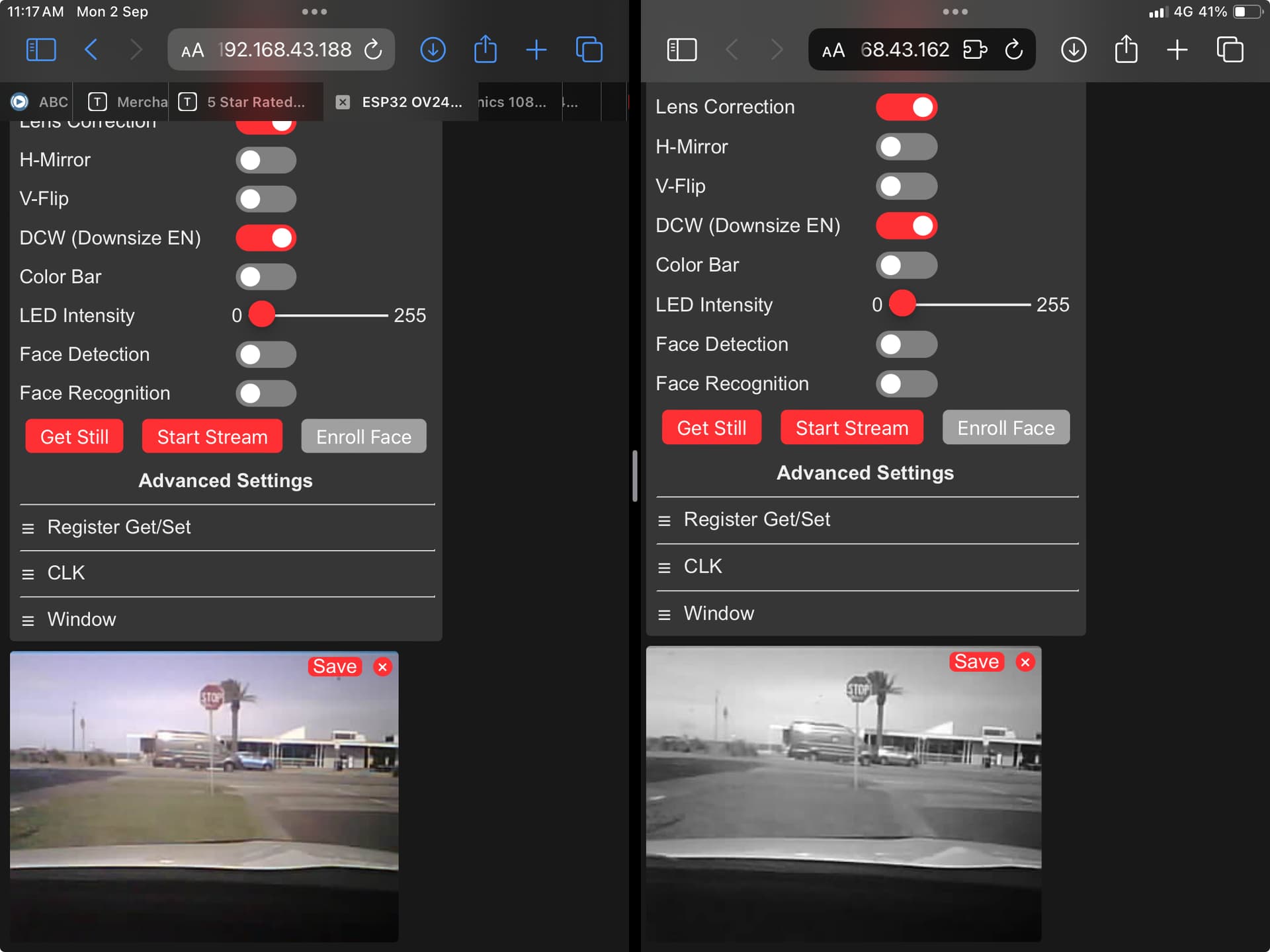
I’ve set up two ESP32-CAM boards right next to each other (5 cm apart) and each feeding a video stream to an iPad (the same iPad). The iPad is running two instances of Safari browser, so the video streams are on the screen side by side. Works fine.
I can grab a still shot from each by touching a button on the appropriate browser. I wanted to see if I can get “simultaneous” shots, say within 0.1 seconds.
I’ve set it up looking at passing traffic (60 km/h) and touch the buttons at the same time. The result is good – I reckon within 0.1 seconds. Here’s a screenshot from the iPad. I’ve set one camera to take gray scale so I can distinguish one from the other. You can see a van coming from the left and just passing the stop sign. I can’t see a (significant) difference between the two images.
I realise this is a long way from taking simultaneous shots from two locations hundreds of metres apart. The range with these ESP boards is disappointing. I think it’s only a few metres. What experience do others have with ESP boards? I was expecting better range than this.