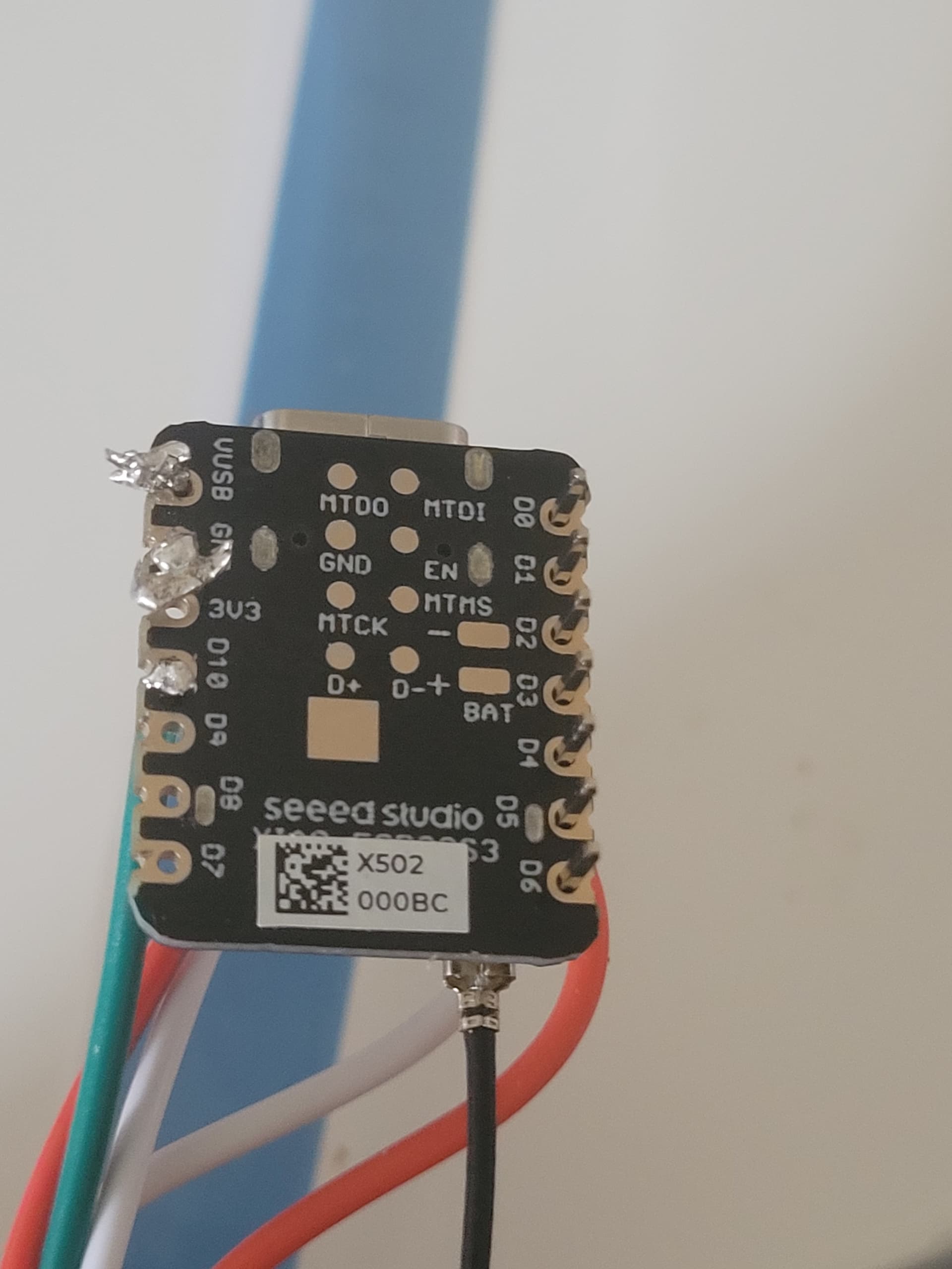
Here’s where the wires were soldered to. I took a page out of your scribbled diagram and another out of the tutorial page that is WLED-related. The wires were inserted into those micro-holes and secured in place with a thick amount of solder. I noticed behind the MCU was a diagram or circuit board. Since the LED strip came with 2 extra long wires with stripped ends (color coded red and white, possibly the 5V and Ground wires?) however there was no sign of a data wire similar to the other two in length. So I cut off the end of the clip on and used the green wire from that part as Data wiring and connected it to the bottom-most hole. I’m not too sure if I should have the ends of those wires completely soldered to the back-most circuit board but given how poorly-arranged the wires are, I’ll let you correct me on this one.
Not sure of the gauge: possibly 18-22? I’ll have to look it up.
'possibly isn’t good enough. You need to be quite certain what they are or things will blow up.
Look closely at the LED strip. There should be labels for the wires. If unsure, you may have to remove some heatshrink at the connections to confirm which wire goes to which contact (the heatshrink can be replaced with some insulating tape). It should look something like this:
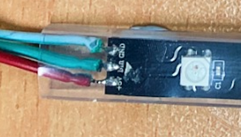
Note the labels: +5V, Din (Data Input) and GND. These are the labels that you use to identify the wires. They might match some colour standard that you are referring to, but they might not - you have to confirm.
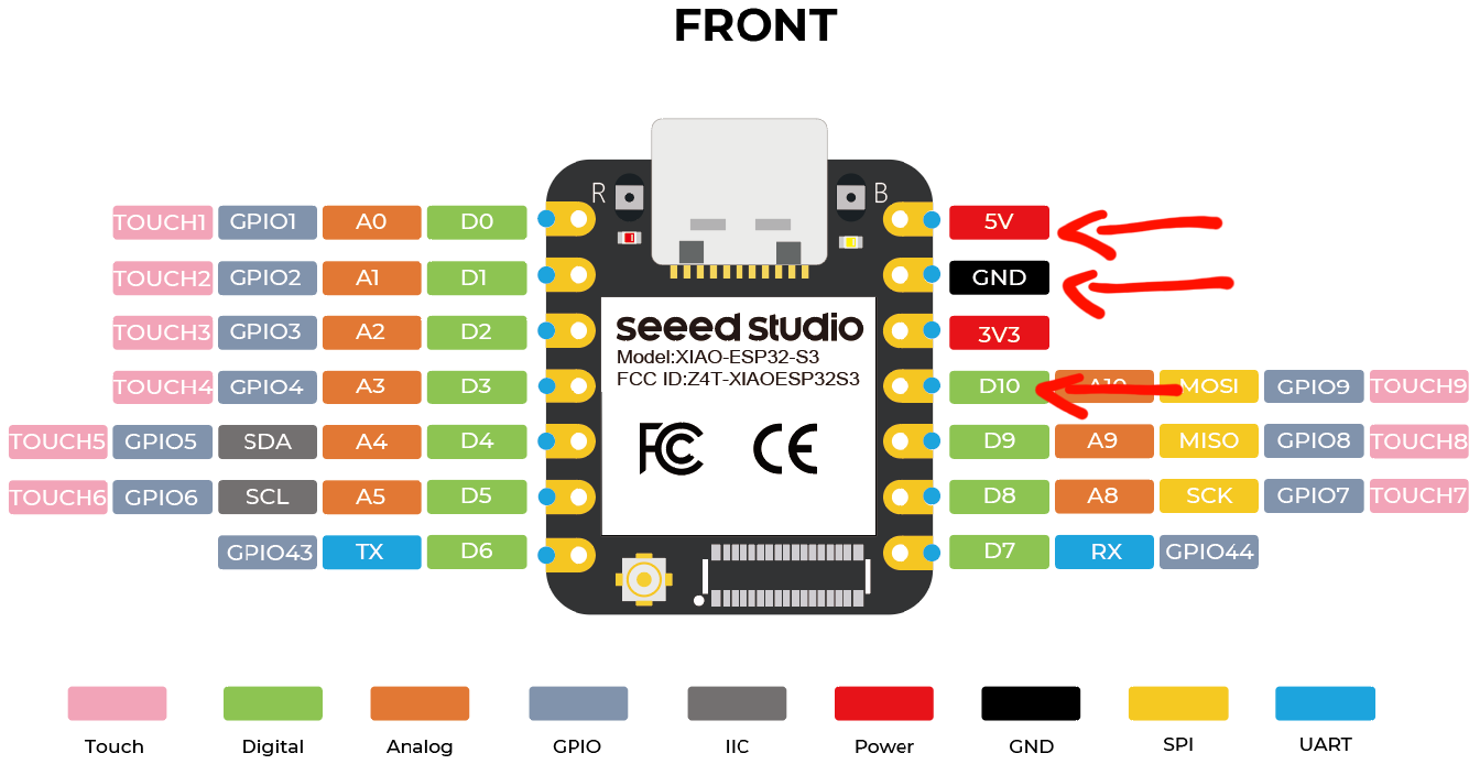
You should not be powering the LEDs from the +5V on the MCU - that arrangement might work for a short while but it will eventually cause you trouble and could damage the MCU. The LEDs must have their own 5V power supply. At this stage you are powering the MCU from the USB port, so you only need to connect ground (because the grounds from the two power supplies need to be connected together) and the signal (Din).
That wire looks much larger than you need for the MCU. It’s suitable for the +5V and Gnd connection to the LED power supply, but you can use much lighter wire for the signal (Din) and the common earth. That will be much easier to connect to the MCU (although I strongly recommend against soldering at this stage).
I can see that from the image. The important point is what they are connected to at the other end!
But note the comment above - the +5V from the LEDs should not be going to the MCU, and the Gnd that connects the two power supplies can be lighter gauge.
It appears from that image the 3V3 and GND are connected. Do NOT power it up like that - you will destroy the MCU.
The thing is, I needed to test the animation patterns, brightness, etc. so without doing that first would mean just skipping the most crucial step; ensuring they power on, go thru a testing phase, and locking in/choosing the animation presets before going for a more complicated setup.
The MCU is what I need to run the WLED firmware, without the LED strip connected it would void everything else. So are you telling me the GND wire is all there needs to be connected (soldered or not) to the MCU? Shouldn’t that be up to the DATA wire, since we are writing the code for animation presets and testing the animations as we go?
No its the 5v5 and GND that are connected, or rather, soldered to the MCU, and not the 3v3 (I’ve left that out as it is obviously not part of the setup process). I only soldered the DATA wire in the hopes of getting it up running and testing/altering the animation presets and brightness.

That sure looks to me like you have the GND and 3V3 connected. Do not try to run it until that connection is removed.
No. What I said is “… you only need to connect ground (because the grounds from the two power supplies need to be connected together) and the signal (Din).” This is possible because the MCU is powered from the USB. When you are not powering it from the USB you will need to make power connections from the MCU power supply, but you do not have to worry about that yet.
That is, for the three wires from the LED strip, two of them, 5V and Gnd, will go to the LED power supply, and the third, signal (Din), will go to the MCU GPIO. Then you will have a ground from the MCU to the LED power supply because all the power supply grounds have to be connected together.
Your comment about what you need for testing doesn’t make sense to me. To prove the concept and start making patterns you need a MCU connected to the PC by USB, so you can program it and also power it. You need a LED strip powered from the LED power supply, and you need the two connected together as described above. And that is most conveniently done using pin headers on the MCU and a solderless prototyping board.
According to this article, testing the app requires all 3 pin wires (DATA, GND and 5V5) connected to the MCU, which presumably is connected to an “external” power source (plug in wall socket not apply?)
- I know my MCU is a different model but similar layout. The article is hinting for a simple app synchronisation and pairing the LED strip. I know they need 2 separate power supplies but if the article states that the following assigned arrangement is sufficient to run the app with the LED strip, I’m not sure how else to agree or disagree with it.
What the others were trying to say when you solder wire to the board it should look more like the following then what you have. This is just a quick test I did to an old broken board, but you should get the idea.
Note: there is no excess wire that could bend fold, fall onto anything else and good adhesion to the pad/via. Sorry did not clean up the flux post solder, but of a hurry.

The wiring diagram in that article shows a MCU without a USB connection to the PC. In that case the power to the MCU is supplied from the external supply, and there will be +5V and Gnd.
That’s not the way you are setting it up - you are supplying power to the MCU through USB, because you want to be able to download the sketches. So you will not have +5V, but Gnd is still needed.
You can do it like they show in the diagram, but you shouldn’t. It will work for small strings of LEDs and for a short time. It will also be unreliable, and the problems that are created can be very difficult to sort out - typically it is random shutdowns or patterns getting confused. You are trying to prove and refine your setup, and those problems will make it impossible to do that effectively. The article you quote is just an example - it’s not the way to configure for testing and development. For every example that says it is OK I can quote any number that say it’s not - and that is probably people who have been bitten once and will not do it again.
I was just looking back at your diagram, and it seems that the extended GND wire is shown to be interconnected to another GND wire, but I couldn’t find a 2-way GND wire to match such a layout/arrangement nor did I find any internally-contained wires inside (assuming its not a set-of combined wires coated with a layer of PVC). Also, would it be practical to solder a USB to 3-pin connector cable that while the MCU (while connected to the LED strip) is USB-connected to a PC, the GND and 5v5 wires (soldered to a USB to 3-pin adapter) is USB-connected to a power outlet-plug. This is to increase time to setup, arrange and demo effects before working on more physically challenging steps. I said before a few times that I intend to use the WLED app instead of Arduino/Python coding to run, test and edit effects, but if you are not sure if using an app instead of a PC software is anyhow practical then I’ll just test them as I go.

I don’t know what a “2-way GND wire” is so I’m not sure what you are looking for. Connect a wire from the LED strip GND to the GND point on the LED power supply. Duplicate that for the 5V wire for the LED strip. The existing wires on the LED strip appear suitable for this, unless you need to make them longer. Then connect a wire from the GND terminal of the MCU to the same GND point on the LED power supply. A finer gauge wire will be OK here, and easier to solder to the MCU. I don’t know what you are using as the LED power supply so I’m not sure how you would make the connection at that end but a simple soldered joint would be fine. Then connect a similar light gauge wire (for ease of soldering) from the MCU GPIO pin to the LED strip Din. As you will be using the USB connection to the MCU to power it, there is no separate Low-capacity Battery Bank so you can ignore that for now.
I’m not sure what you are trying to achieve with this. Are you saying that you want to use a USB adapter as the LED power supply? That is not recommended, as most any USB adapters will be limited to 500mA, and many can’t do even that. That will work for small strips but for any realistic effects you will almost certainly exceed that load, unless you keep the display quite dim. You could use a USB lead (with two wires, not 3) to get 5V and Gnd from an adapter if you wanted to go that route, but it would be easier and cheaper just to cut off the USB connector and solder direct onto the adapter wires. However there are generic 5V adapters with higher current capability available, and they have the advantage of a proper power plug. That would be quite suitable to use during development.
You will only know which one you should be using if you try both.
If you look at your diagram it seems the MCU and the low capacity battery bank is connected to each other by a GND wire with what I assume to be another GND wire in-between that cable. Or it could be two GND wires with one connected to the MCU while the other connected to the low capacity battery bank coming from the LED strip.
Temporary power supply. Since I currently do not have any 18650 batteries nor a holder for them and I still need to test the LED strip, make sure it powers on and choose and alter animation sequences and it connects to an app, etc. I assumed a power outlet (walls for example) would provide more than enough power for long-term use. Unless its better to connect it to a couple of 18650 batteries but I would end up using it to waste and they aren’t rechargeable.
That’s correct. The MCU GND, the LED power supply GND and the LED GND are all connected together. I still don’t know what a “2-way GND wire” is but I don’t think it matters. Connect them together like I suggested and you are good to go.
You can’t make that assumption. 240V to 5V adapters come in a huge range of capacities. Just choose one that is suitable for what you are trying to do. If you are only going to be testing individual lengths not much more than 1M then I think 2A would be adequate, but a 4A like I recommended would be much better and not much more expensive.
What I meant was: how can a GND wire connect itself to the middle of an existing GND wire that already connects the MCU and lower capacity battery bank when its supposed to connect to a GPIO? All wires are just one linear end to end, your diagram makes it look like the GND wire from the LED strip is connected to the middle of another GND wire that connects the MCU and low capacity battery bank. If branching isn’t easy enough to explain what I’m seeing in your wire layout then I don’t know what else will.
Again, the LED strips I use are all max. 1M long with a total of 144 LEDs per strip. Are you implying that there are 2A, 4A adapters for wall plugs/power outlets that can be used for USB plugs?
Another issue I ran into: I soldered only the GND wire (the longer one that comes with the LED strip) and removed all other wires to the MCU, then plugged the MCU via USB connection to the PC. The MCU red light indicator lit up for a few seconds, then goes off, but the MCU and LED strip doesn’t show up on wifi connections list. The serial port also no longer shows up, and I’m not sure if the MCU requires a reset, or if there’s some physical defect by unknown causes.
The diagram shows what needs to be connected together - it doesn’t show how you have to connect it. A wire just establishes a connection between two points. If two wires have a common point then, for this purpose, it makes no difference whether you make the connection at this end, the other end or somewhere in the middle. All that matters is that each end point is connected to each other end point. If you want to connect the GND from the MCU to the middle of the wire from the LED PS to the LED strip, as per the diagram, go right ahead. That might be the best strategy if there is already a join at that point, such as would be the case if the LED PS used wires instead of terminals. But if the PS has terminals then it probably makes more sense to connect the MCU GND at the terminal. Unless that’s a long way away and it is easier to connect it the GND on the LED strip (but that’s a very small soldering point). What I would not recommend is to make the common point at the MCU, as that soldering needs to be very precise and the wires would be too big for the pads. But it’s all the same as far as the connections are concerned.
Yes - but is it possible you might want to be testing two or more at once to see the effect? You need to be sure that your configuration will do what is needed for the project development, but 500mA from a USB wall wart isn’t going to hack it. The 2A or 4A or higher 240V to 5V adapters can be used with any connector, but if you need that sort of current I wouldn’t wire them up to USB connectors because I don’t think USB connectors are rated for that capacity. It might work, but they might overheat and melt. But why would you want to use USB connectors for power?
Does that mean that you got WLED installed and accessible from your PC browser? That little bit of progress hasn’t been mentioned. But if it worked once it will work again, unless something has changed. Are you sure there are no remnants from your soldering that left a bridge between two of the pads? Powering off the MCU will reset it, but you might have to put it into flash mode at the next powerup. Reinstall WLED onto the MCU and see if the device appears again in the WiFi list.
The WLED installed was meant to be for app/web interface use, no PC software was installed. But thru changing the wire layout from the extended 5v5 and GND wires soldered to the MCU to changing it to the main 3 connected wires from the middle of the LED strip to just connecting the GND extended wire and disconnect all other wires has left a bit of a mess, with bits of solder and tiny-scale burns on the surface, though it doesn’t or does seem to affect the functionality of the MCU I’m not certain. I had to literally remove/clean off the GPIO holes and surrounding area of excessive solder-related mess, since I had been connecting wires by inserting them thru the relevant GPIO holes before securing the copper ends with a thick bit of solder.
2 is the max I will test at a time, but right now my focus is to actually get the LED strip to power up and demo any animation effects to get a headstart that will point me at the right direction, which is an unresolved challenge as of now.
Because there are only 2 options for a secondary power: connecting to 2x 18650 batteries via a soldered battery pack or soldering a 3-pin USB adapter. Since the MCU and the LED strip as you said cannot share the same power supply, I had to think of where else I can source the secondary power while one is connected to a PC. Hence the USB adapter for a USB wall power outlet plug as one of the plausible ways to get it to function and test to some extent. If I end up using 2 18650 batteries and I used up all of its power on testing animation and power tests it would be a waste, and I would overspend on another bunch of 18650 batteries which would end up with the same result and waste more power, plus 18650 batteries are not rechargeable, I guess? Either way, the ends of the 3 main wires attached to the LED strip (Red-5v5, white-GND, green-DATA) has to attach itself to something (since we are cutting off the connector 3-pin plug it comes with) , what else would you suggest besides soldering a 18650 battery pack to it or substitute a USB plug for power outlets?
Again, not sure what you mean by “terminal”. Theres only wires that have no “joints”. If the GND wires are to connect somewhere in the middle of another GND wires, might as well cut those “middle points” off, strip those wires and solder 3 wire ends into a central joint. That is the only plausible way I can think of since “joint” wires don’t exist (or do they?) Every wire I had ever seen or known (despite AWG size) has only been single linear and never another wire protruding/connected to the middle of another wire. How can you tell me if there’s wires that already come with one single end on one side but with 2 ends on the other, while covered in PVC?