Yeah, too late in the day for an Friday, the states of A and B in receive mode.
Due to this auto being (what looks more like a hack) is why I was tempted to go full manual and trigger rx/tx mode via the mosfet. that way we know its in full transmit mode.
Hi Michael
Matthew has stated above his traffic is only one way.
So for permanent TX mode remove the Mosfet. Job done.
Cheers Bob
And like I just said. Remove the terminating resistor and terminate at the receiver end if not already fitted internally.
1 Like
Lets let bob lead here (too many cooks).
I like the idea of full manual, via your pin 17, so that would need R6 removed and put in R7.
i.e.

But lets see what bob thinks and flow his lead or we will end up in a mess
Yep…
Is this a 1:1 connection? I think it was via the mux ?
Matthew previous diagram shows it connected directly connected to the Shipmodul “NEMA IN” connection which is RS422 compliant or so the text says.
Cheers Bob
Re your diagram yes that would work if R6 removed and the logic driving GPIO17 was reversed. I was thinking more along the lines of having one less thing to worry about.
Just transfer R6 to R7 position
So the intention guys is just to transmit a WPL message to the Garmin MFD.
That Waypoint message is a vessel in distress. I wanted to automate it so our radio operators and boat crews dont have confusion with Lat / Lon conversions etc.
I feel I owe you since you have been so helpful to provide more information.
2 years ago I wrote an app (web based) called DV Locate. You can google it.
When I first wrote it I demonstrated to Marine Rescue NSW of which I am a member of.
The Marine Rescue NSW Board loved it and bought the rights from me.
They commented that it would be great if the DV (Distressed Vessel) could transmit the Lat long directly to our rescue vessels MFD (Multi-function Display). ie" The lat long without human intervention.
DV Locate is in use across the entire NSW east coast and saves lives.
So I have been looking into NMEA0183 to deliver a named Waypoint to our vessels automatically.
Cheers
Matt
1 Like
Hi Matthew, Michael
What a worthwhile project. Congratulations.
Now see if we can help further.
My order arrived and I have been having a play yesterday and today.
The RS485 devices I got are Core SKU CE05154. The description and schematic are on Core web site so will not elaborate here.
The test equipment used was Unit-T function generator and a FNIRSI tablet CRO. I suspect the CRO measurements are a bit high in amplitude but I know about this and can live with it. Very portable and does the job I want it to do. Nothing fancy.
Converter 1 set up as transmitter by leaving DE and RE as is connected to Vcc via R2 and R3 10kΩ pull ups.
Pic 1is the data input signal. Repetitive square wave at 2.4kHz (4800 baud) set at 40% duty cycle to enable identification regarding the phases of line A and B.

Pic 2 is the line A and B output. Output pull up/down R5 and R6 and termination R7 in place
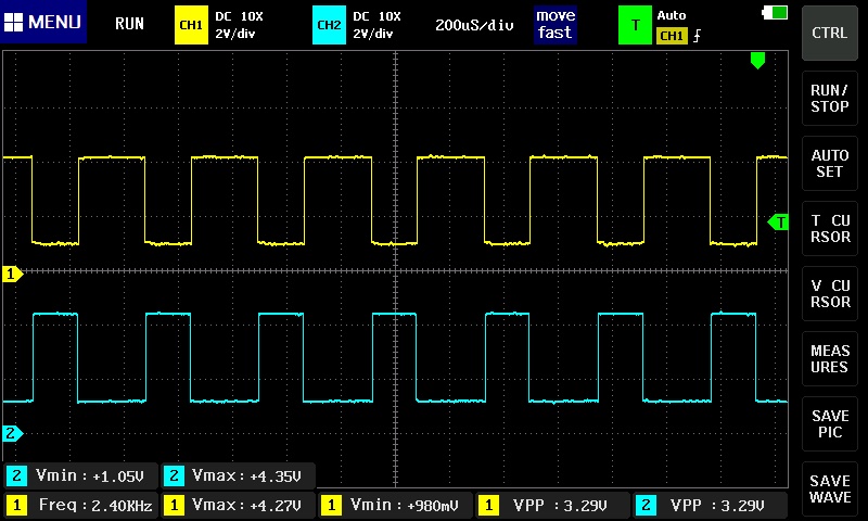
I accidentally connected the probes to the wrong outputs here and did not notice until too late so chan 2 (blue trace) is line A and chan 1 (yellow trace) is line B. Just keep this in mind as I have left it like this until finished with line measurement.
Pic 3 is the A and B output with pull up/ down resistors R5 and R6 removed.
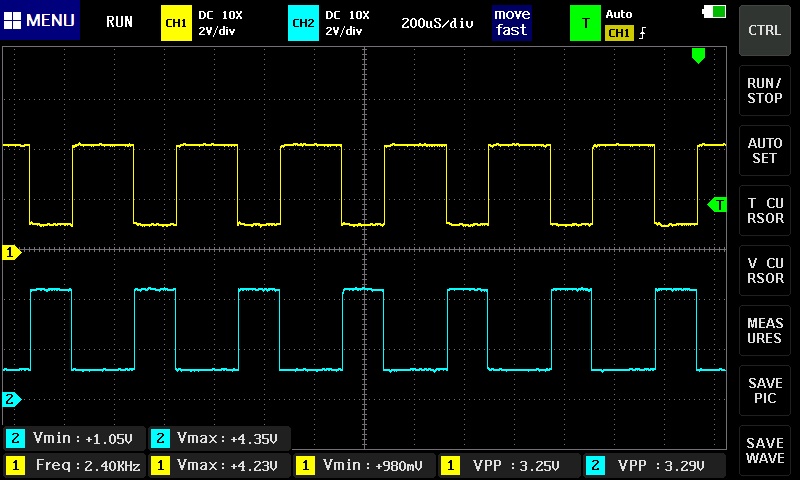
As you can see there is no apparent difference. I think they are fitted as some sort of fail safe system but with the latest chips they are not necessary as mentioned in the RS485 data sheet.
Quote
“The receiver input has a fail-safe feature that guarantees a logic-high output if the input is open circuit.”
End quote.
Pic 4 is the same with terminating resistor removed. This termination is only required at the receiving end of the line cable and only used here in half duplex operation when both ends of the line are receivers. Does not apply to your situation.

I then configured a second device as receive only by joining RE and DE then to ground. I left the terminating resistor R7 and the biasing resistors R5 and R6 in circuit. Devices connected via about 4 metres of plain figure 8 pair.
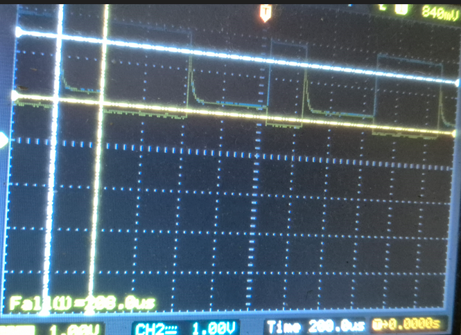
Pic 5 is Line A and B at the Receiver input with no data input.

Note Line A is HIGH.
Pic 6 is line A and B with data restored.

All good so far.
Pic 7 is overall. Ch 1 (yellow) is the data input to DI on the transmitting device and Ch 2 (blue) is the final output RO of the receiving device.

As you can see a very faithful reproduction of the input.
For completeness pic 8 is the same with Vcc 3.3 - 3.5V and input 3.3V. Although the MAX485 is basically a 5V device it seems to operate OK at the lower voltage. Not recommended though.

As said the MAX485 is basically a 5V thing but the chips you have in your converters are a 3.3V version so you should see the same as this experiment. If you don’t there is something radically wrong.
I would suggest you use the AB Electronics Hat which has not got the line biasing resistors but you should remove the terminating resistor R3. If the receiver (RS422) has not got a resistor already fitted you will need to fit a 120Ω resistor at the receiver end of the cable.
If you want to control the TX/RX function of the Hat for some reason with GPIO17 you need to remove R6 (0Ω) and fit it to R7 position or put a small wire link in place of R7. If you want to make the transmit function permanent just remove the Mosfet.
I hope this makes some sense. Let us know please.
Cheers Bob
Hi Robert,
Thank you for taking the time to do this and for kindly providing the detailed results.
I dont have a function generator so I’m kind of thinking what’s the next best step at my end ?
I have both SKU: CE07496 & SKU: WS-14882
Knowing what you know now for 1 way transmission from RPIZero 2 W + (one of the two hats purchased) to the Shipmodul may I ask what you recommend as best practice ?
Which SKU would you advise or even a different SKU if we put the CRO readings (or lack of me using the CRO correctly) aside ?
Cheers
Matt
Hi Matthew
A useful instrument but not a big deal. You obviously got some input data from somewhere to come up with the CRO displays. I imagine from the RPi device. That will do.
How to go about this??
I would use SKU: CE07496.
Your traffic is one way so you can tie RE and DE permanently high to enable transmit only.
Remove R6 (0Ω).
Then you can remove the Mosfet or connect the Gate to Gnd to prevent it switching.
If for some reason you wish to control TX/RX selection using GPIO 17 fit the R6 resistor (0Ω) in R7 position or fit a wire link in R7 position. I don’t know why you would want to do this as your Shipmodul is one way only. The Shipmodul is RS422 so is one way traffic only. This will require a LOW at GPIO 17 to transmit.
R5 is non effective in this set up so remove it. The terminating resistor has to be at the receiving end of the A/B cable so will require a 120Ω resistor across the A and B at the Shipmodul input. It is possible that there is already a termination built in. To check this measure the resistance (with power off) between A and B. If you see about 100Ω the termination exists so don’t worry about it. If not you will have to fit the resistor.
Due to your practical involvement here you will be well aware that these bits are going to be introduced into a VERY harsh and hostile environment. On a boat in mostly very inclement conditions. The important thing here is these components are usually Hobby quality and not really designed for this sort of use.
With this in mind I firstly WOULD NOT use the DE9 connsctor. This would probably be of domestic quality and might last the proverbial 5 minutes. At the very least you would need Mil-Spec quality with the heavier gold plating on contact surfaces. This then passes on the required soldering techniques as gold is not considered to be a high reliable solder joint. I would solder directly to the A, B and Gnd connecting points provided at the end of the board.
The connecting cable also has to be protected from the environment and has to be of suitable quality. Then the whole lot has to be kept dry and away from all the nasties. Some form of conformal coating on these boards would be a good idea when everything is in place.
Grounding. You might find that installed equipment ground is separate to the Radio ground. This should be a flat copper strap connected to a chunk of gold plated metal on the outside of the hull (assuming a fibreglass or non steel hull). The radio ground has to be in contact with the sea as it is the sea that provides the counterpoise for the antenna system. If this is the case stay right away from this ground and use the same ground as other devices.
As well as the A and B wires you might need a ground connection from your RPi / RS485 set up to the Shipmodul.
I would strongly suggest you have a look at these publications.
and.
I think I have already posted these links but have done so again.
Cheers Bob
1 Like
Hi Matthew
You seem to have gone very quiet or busy.
Have you resolved your RS485 issues??? I (and probably several others) would be interested in any result.
The rather long response to this query above I don’t apologise for. It is to outline potential problems as I personally see at the moment. Not to discourage you in any way but to highlight what I see important provisions that can be used to minimise future problems. Particularly, as you might have noticed, material quality in hostile environments and the possible need for some form of conformal coating to help “tropic proof” all the bits.
Don’t be discouraged by all this. It is not that hard if you think about it and be careful. I may seem to have gone overboard with this but I would hate to see what is a very worthwhile project fail due to an easily avoidable problem with an environmental caused failure.
I had a rethink about the Radio earth contacting the sea, I don’t know comms details but being coastal your vessel comms could be all VHF in which case the antennas would have their own ground plane or counterpoise. If this is the case the gold plated “earth” device may not be fitted. It is important though for HF (2 - 30MHz) antenna systems.
Let us know how you are getting on. I for one am interested.
Cheers Bob
1 Like
Hey Robert,
I kind of got dejected even after following instructions to bridge connections and install resistors etc etc I didn’t see any change. No message received.
And that’s on me so sorry for that.
Cheers
Matt
Hi Matthew
Yes I can see how you would get a bit disillusioned after all this time.
But if you can break it down into sections it will become easier.
Firstly you have to get your message from A to B. That means your RS485 system has to work. It has to look like the results I got above with my simple units configured as a dedicated TX and RX. All seemed good and pretty straight forward.
Having achieved that, provided your message is valid and the Shipmodul is doing what is expected all should be good. This bit I am afraid is up to you. BUT if the RS485 /RS422 system is not doing its bit then nothing will work. That to me is the simplest bit.
Not knowing exactly what you are doing or how you are doing it is proving very difficult without being able to actually see your problem. Core seem to have removed the messaging system so it does not seem possible to message privately and Core frown on (quite correctly) posting contact details. I am suggesting that if you don’t live far away it might be possible to have a face to face look at this dilemma. If you approach Core they might be able to give you my Email address and we can make contact.
Cheers Bob