That looks better. Makes a lot more sense. Not so much strain on Vin now.
Cheers Bob
4 Likes
Hi Bob,
Yeah a lot less ahaha, onto making the footprints now. Will keep the topic and repo updated!
1 Like
Day 8 - Final testing and updates
I got my order from Core yesterday and everything was perfect!! The devboards are here and I’m starting to test the code as we speak, the pin numbering will obviously change a bit but the main test is if ESP-NOW’s micropython port works.
Yesterday was a rest day (A rule I have is never rest 2 days in a row)
Changes for the new chip:
When erasing and flashing the --chip argument changes to ‘esp32-c3’ instead of the default ‘esp32’
A new version of firmware has to be flashed for the RISC-V architecture.
Erasing flash:
esptool --chip esp32-c3 --port COM4 erase_flash
Flashing
Ensure that the flash location is ‘0x0’
esptool --chip esp32-c3 --port COM4 --baud 460800 write_flash -z 0x0 firmware-esp32-GENERIC_C3.bin
esptool --chip esp32-c3 --port COM4 --baud 460800 write_flash -z 0x1000 firmware-esp32-GENERIC_C3.bin
EDIT: The code can be flashed on but only one message is received then some undefinined characters

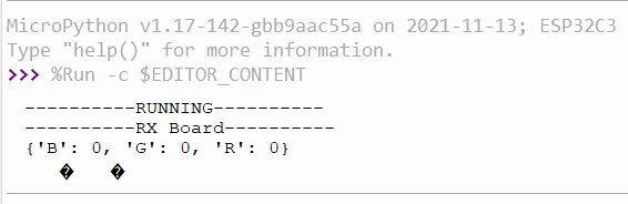
.
Update: The transmit portion seems to work
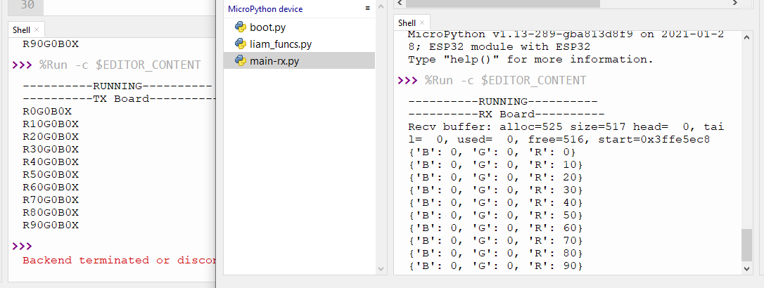
EDIT: Both TX and RX were working from the board, there must’ve been an issue with my library so I have temporarily removed it from the main file
5 Likes
Day 9 - PCB Designs
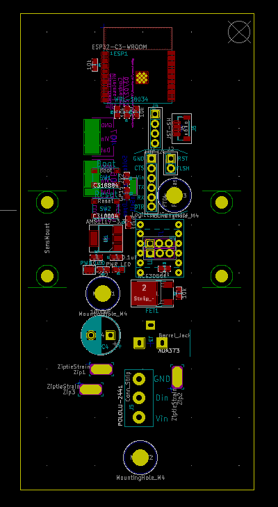
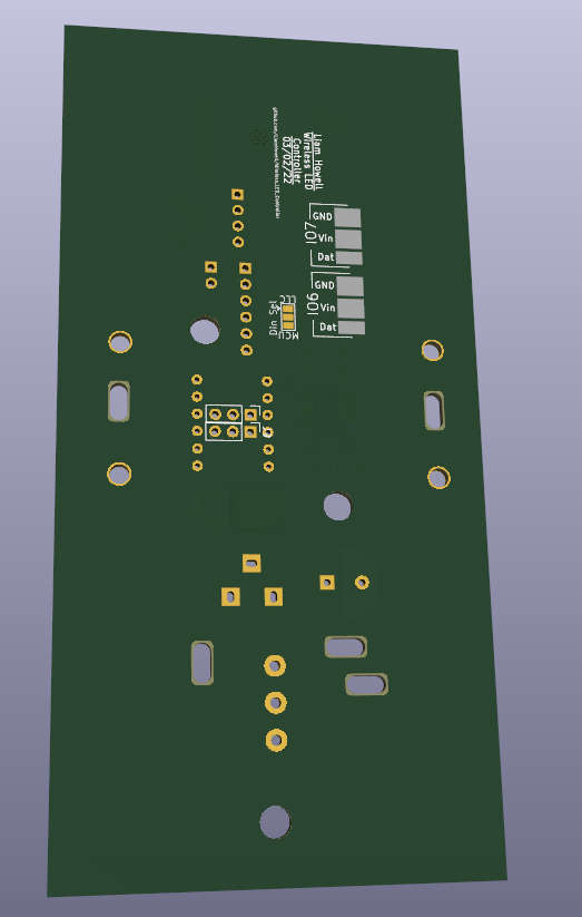
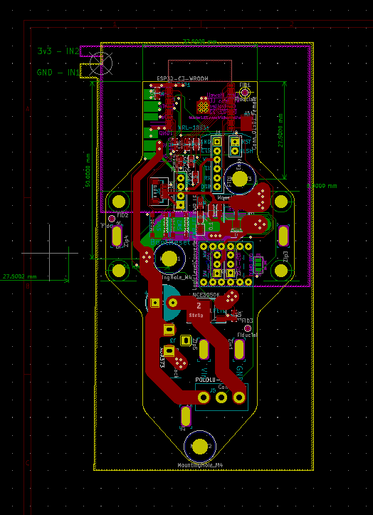
The PCB is almost done and ready to be sent off, a few more changes to the overall shape and some general cleaning is next on the list.
I hope that the module is somewhat PiicoDev compatible, the mechanical connections spanning the middle can act as a mounting point for a couple of modules, a double module, or a mounting point for the entire thing).
The IO connections on the side will allow for servo’s to be connected so the modules have some sort of control - the MOSFET is also available if you don’t have any LEDs mounted (A single-direction motor driver? A Pump?)
Overall it’s about 110mm long, nominally 30mm wide and in the middle section it will be about 55mm wide.

Still todo:
- Clean up the components - I’m not sure if the IO pads on the back have copper underneath or SS
- Tune the profile of the board, clean up the placement and try and shrink it a bit
- Run the traces
- Make it look super cool
- Physically print out the plot files to trace out the wiring to confirm there arent any other errors in the circuit (Thanks for noticing the one before @Robert93820 !!)
- Pay for the PCB’s and assembly service and wait nervously
- ???
- Success?
5 Likes
Day 10 - Final V1 Revision
The PCB is almost ready to be sent off - I discovered a cute little hack to make rounds on your PCB, its a bit messy but gets the job done quickly.
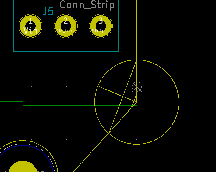
- Create a circle as a guide, the of the round will be close to what the radius of this initial circle is
- Make a segment where the circle intersects the edges of the PCB
- From the centre of the segment create a line to the center of the circle, then extend the line to the circumference
- Use the arc tool to scribe a line, you may have to readjust the line that isn’t parallel to the horizontal or parallel planes
4 Likes
Day 11 - Nearing the end
I’ve reserved my final day for soldering and programming the actual PCB’s so this will be the last update for a little while, the PCB design is complete, I just have to update the dimension drawings, upload the gerbers to JLC along with the BOM and P&P files.


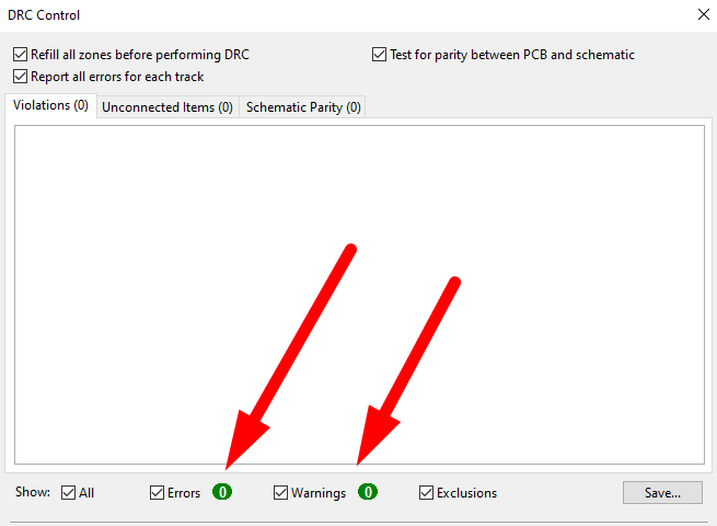
And the ooh so satisfying '0 DRC errors'..
Should have read the errors on my last PCB design 
There’s still a bit of housecleaning to do in the GitHub repo and making sure the ESP-NOW packets are correctly unpacked - both for LED strips and sensor data (A parallel into a smart home system).
This is a majority complete - I’d say around 85% so will close off here.
If anyone has any questions while the PCB’s are being shipped lemme know! 
Update: The PCB has been sent off! I updated a couple of values around the resistors current limiting resistor (from 22k ohms- waaaaaaay too high down to 660 ohms which maxes the inrush current to 5mA)
9 Likes
Hey Liam,
Nice write-up, that notes section on the PCB is a great idea for smarthome systems! Can’t wait to see the finished boards
Liam.
3 Likes
Fantastic write up, really excited to see the finished project.
2 Likes
Cheers Kory, me too.
If you wanna check out all of the files here’s a link to the repo: GitHub - LiamHowell/Wireless_LED_Controller
The PCB’s are almost done now, then should be 3 days for SMT assembly - hopefully I can wrap this one up soon!
5 Likes
The PCB's have arrived
After probing around with my DMM looking for shorts I’ve for 14 working boards and one fail (Vin is shorted to 3v3).
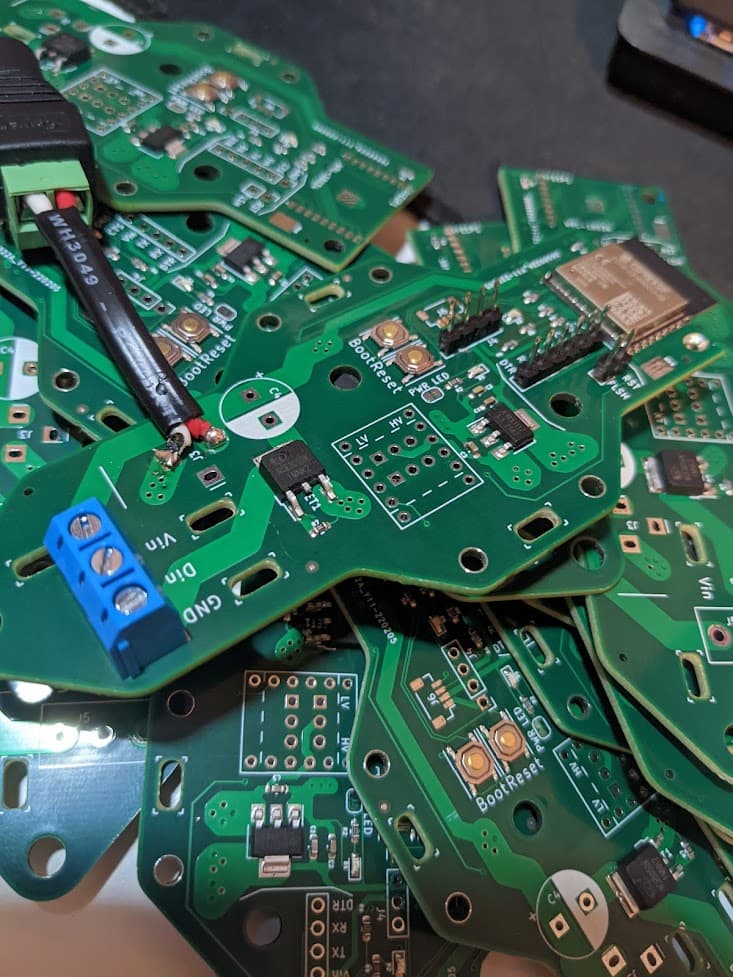
I’ve popped on together with parts I had lying around to see if it at least powers on and the power LED is working!
I mistimed my Core order to get parts (oops), should have picked up one round of parts before the project.
During the wait I was thinking about being able to use a Pico as a replacement for the CP2104 onboard ($10 vs $5 isn’t a big deal but repurposing a board would be neat and a good exercise for the PIO)
But am unsure where to start - I’ll add it to the list.
5 Likes
Trying to design the programmer extension
While I’m waiting for the last Core order to arrive I’ve started scoping out emulating the auto-reset circuit that’s attached to the CP2104 USB-Serial programmer.

Full circuit diagram
I picked up a transistor pack and am trying to land on a usable transistor for the two used on the dev boards auto-reset circuit
Transistor on the ESP-dev board
After taking a read through this amazing forum topic I’ve got some pointers as to what exactly it does - in short it’s an XOR(backed gate that seamlessly handles the resetting of the board.
Quick aside
Upon further reading it seems to be one method that has stuck for some reason, it depends on the software programming tool being used to toggle the DTR and RTS pins, none the less it will be made on a protoboard so no massive cost to me.
Whats the worst that can happen? I learn something?
Also Sparkfun has a good intro to transistors
There is one improvement though, the reset pins timing is being abused so I’ll throw in a capacitor as suggested in the topic to try and increase the delay on CHIP_PU/the Enable pin. see slightly updated schematic:

Inevitably I’ll be back when it doesn’t work. ETA on the pogo pins and an update are tomorrow ![]()
3 Likes
Intersting soldering adventure
Soooo uuuh, I spent a long while soldering to make something look alright. @Robert93820’s KISS method could have saved so much time and I’ll most likely spin up one on a full-size protoboard to replace this one but it looks neato.
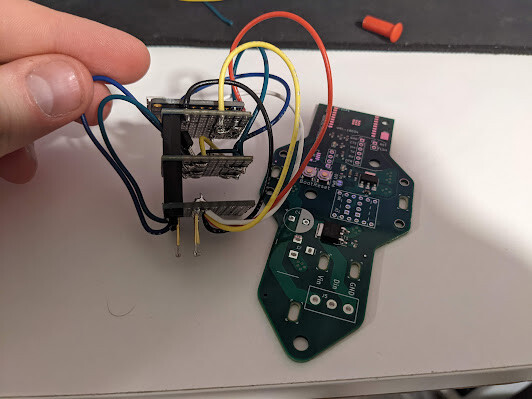
The idea was to have top layer with the CP2014 programmer then the next layer down with the transistors and the layer below that with the pogo pins.
Lesson learnt, the process should have been breadboard → full size protoboard → something that looks cool??
This idea originated from the idea that the mounting pattern could be used to secure the programming module to the board to develop a program then send it off into the wild - for the V2 PCB I’ll figure out something a lot neater.
4 Likes
Hi Liam
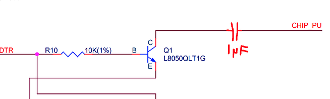
Not too sure what this circuit is doing but this capacitor will remove the DC connection to “CHIP_PU”.
You will probably just have a pulse of whatever and then revert to open circuit.
Cheers Bob
3 Likes
Hi Bob,
I can confirm I’ve botched the circuit, hadn’t paid enough attention to the schematic on the other forum post and put it inline to the signal vs tied to ground. Cheers for pointing that out - I’m sure you just saved me bashing my head against the desk for a while.
The idea was to slow the rise time of the ‘CHIP_PU’ pin a bit.
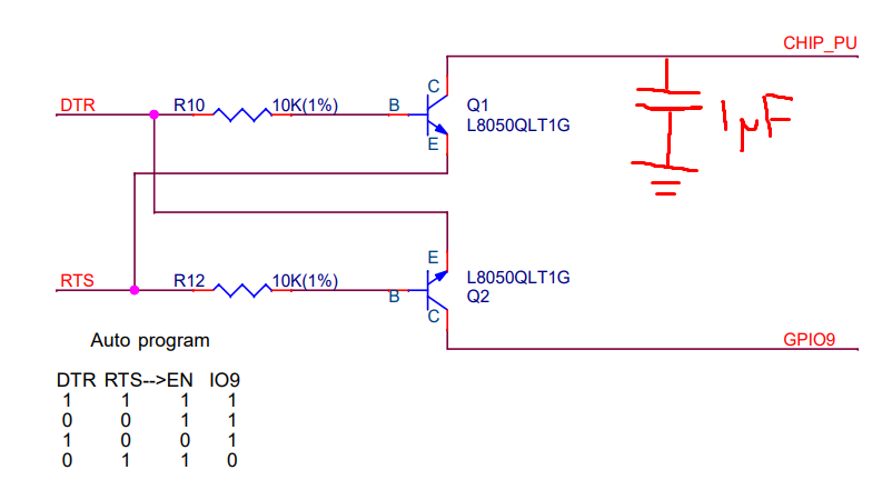
Simulated circuit: (the 10k is on the PCB

The correct circuit
I’ve got some ideas for a V2 so I’ll get this batch working and get the updated one sent off (won’t have to stuff around with designing a programmer on a protoboard)
2 Likes
Hi Liam
That looks a bit better. I am assuming the 10k shown in the simulation is the chip pull up resistor. R10 in your circuit plays no part in any delay and should be considered as part of the switch. The only down side to this is the transistor has to dump the capacitor charge with no current limiting resistor. I had a look at some sort of data sheet for this device and it really tells nine tenths of nothing, except that it can pass 1.5A continuously. May be OK.
Fitting any current limiting resistor in series with the switch will form a voltage divider with the 10k pull up and lift the lowest voltage to the chip. When you will already have a small voltage drop across the transistor this extra may be too high for the chip to see it as a logic LOW. Just something to bear in mind. With this 3.3V logic everyone is keen on these days you can’t have too many of these little voltage drops adding up before you start getting into an embarrassing or iffy situation.
I suppose this 3.3V logic could give one a warm feeling as far as a green planet is concerned but you can get the same feeling wetting your pants in frustration when something doesn’t work as planned. Personally, if I need to fiddle with things such as this I much prefer the extra bit of head room that 5V logic gives you. Particularly if diodes are needed. The 0.6V drop plus any other little bits can be a problem with only 3.3V available. If any sort of current is involved the drop across a transistor can be significant (some drop is always there) and should not be ignored. If it is only a switch sometimes a FET is a better choice for this reason. The down side to a FET is the gate capacitor has to be discharged in a positive manner, not left floating
Cheers Bob
4 Likes
Hi Bob,
Thanks heaps for the help!
Yeah, the documentation isn’t great. With it being a logic output I was thinking of limiting it to the milliamps range, to get it done quickly I’ll remove the cap as to try and not break the programmer.
Personally I do like the 5V of the old Uno but the ESP32 and Pico have micropython which makes programming a lot faster.
Great point about the voltage drops adding up, I’ve run into an issue here and there for that reason.
In terms of over all energy saving from 3.3 to 5v, it wouldn’t have much of an effect would it? Could be wrong here; optimisations to circuits and programming would fix most of that. Less beginner friendly for sure.
Thanks again for all of your help!
2 Likes
Hi Liam
One other thing. What sort of repetitive frequency are we talking about here?? 15msec seems like a lot of delay. you would be lucky to handle anything over 50Hz (20msec) at that rate. As you have labeled inputs as DTR and RTS I assume some form of serial coms. 15msec would swallow up a lot of data time.
Cheers Bob
3 Likes
Hi Bob,
The DTR and RTS pins are just the auto-reset circuit so only get pulsed as required (to enter the flashing mode and exit flashing takes between 2 to 5 seconds so plenty of time to discharge but not sure if that puts the microcontroller in some unexpected state).
Understood, I’ve ditched the capacitor and gone for the reference circuit that a lot of boards use (without the cap) I’ll keep the topic updated if anything breaks
2 Likes
The Inevitable...
I haven’t got the board to work just yet and only just starting the troubleshooting/learning journey.
Things that I’ve taken a look at so far:
- Solder connections - they look fine mechanically and there arent any key shorts
- The Schematic - I’m don’t have a lot of experience with the hardware side of the ESP32 but it looks close to the devboard I was using before
- Continuity and voltage levels - I probed the GND, Vcc, RX, TX, RST and BOOT pins on the ESP and haven’t found anything unexpected
Moving forward to understand how to set up an ESP32 a bit better I’ll make a breakout board for the C3 variant for breadboard/protoboard and another for the full-sized module (unsure which exactly)
Other steps to try and get it working
- Reading the input of the serial connection with a oscilloscope to see if there is any distortion that could cause a bad read
Upgrades for V2
- Make some easier to access test points, a through-hole test point lets you poke the PCB with the DMM probes
- Protect the ESP32 a bit better
- Make some of the pads a bit easier to hand solder - a little bit larger doesn’t hurt
- Use understood off the shelf parts as much as possible for a rev1 - the programmer is a good example, I just stumbled across the ESP-PROG and will be using that board from the next rev
- Most likely breaking the different ‘modules’ out from each other (there are definitely two different functions to the board, the microcontroller end, and the MOSFET, isolating the two and using some swiss headers will let me test both individually)
5 Likes
Where to from here
I’ve sent off for some ESP32-C3 breakouts and in checking out Core’s New Products feed I noticed a breakout board for them which is feature-packed (got some on order).
The project has blown well over the 12-day mark but in spending some time away from it and having a good rescope I think I’ve landed on an idea that is a bit more usable for other projects.
The wireless portion can be handled either as an I2C slave or serial endpoint.
5 Likes