This is a placeholder topic for “5V Single Channel Relay Module 10A” comments.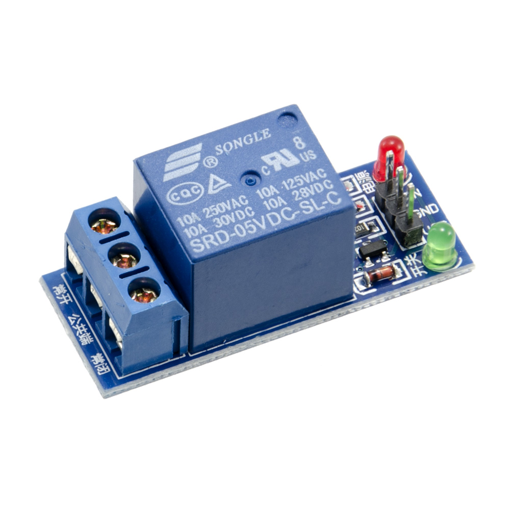
A versatile relay board with opto-isolated input. The relay channel can drive up to 10A @28VDC
Read more
1 Like
Does this board have a flyback diode built-in? Can it switch low amp 24v AC power?
2 Likes
Hi Patrick
The relay markings say 10A @ 250VAC and 10A @ 30VDC so that should answer one question.
The data sheet for the actual relay does not show a diode but the pic shows a diode near the green LED. With no circuit available this could be anything. The black blob immediately above this diode looks like a transistor or optocoupler so it would probably be the flywheel diode. It would be oretty slack of the board manufacturer not to include this. But it IS Chinese…
Cheers Bob
4 Likes
When I received my relay didn’t come with headers as shown in the photograph. I tried soldering on without success. Is this normal should it come with headers for power, ground and data?
1 Like
Hi Adrian
Soldering or headers, it should not make any difference unless the soldering job is a bit flaky or suspect. Headers would probably be supplied loose so you would have to solder them anyway.
It is still a bit slack though when the pic shows headers fitted. A good philosophy would be if they are not included don’t show them. A little bit of misrepresentation.
Cheers Bob
1 Like
If you mean that you couldn’t get the solder to wick onto the headers, so it was always a dry joint, then this is normal. These headers usually need a good scraping with a sharp blade before they can be soldered, even when using a good flux.
1 Like
Can I control this relay with a Raspberry Pi, even though its GPIO only output 3.3V?
Hi Tony,
Welcome to the forum ![]()
The manufacturer’s specs have designed these modules for 5V operation but we’ve found during our bench testing here that they’ll work fine at 3.3V as well.
Keep in mind the power supply to the module should also be 3.3V if you’re trying to run it at 3.3V logic levels.
Also, this relay is active low, so pulling the signal pin to 0V engages the relay.
Hi Trent
That might be so but I think it is a pretty bold statement to think that ALL of these modules will be reliable at 3.3V.
The Songle data sheet says pull in is 75% Max and release is 10% Min. Some relay manufacturers quote Min pull in voltage That is the minimum voltage guaranteed to operate the device and Max voltage the relay is guaranteed operate before release. From that I assume this unit “must operate” voltage is 75% of rating (3.75V) and release max is 10% (0.5V)
Now admittedly 3.3V is not far below the “must operate” point but you must factor in the voltage drop across the opto transistor which could be anywhere between 0.2V and 0.3V or even higher. This may or may not vary somewhat with opto LED intensity if the transistor does not switch hard on (darlington opts are better in this area) but as the info regarding the circuit and opto type are unknown and look like staying that way accurate forecasting is a bit difficult.
The point I am making is that when you subtract this voltage drop from 3.3V there is not much left and it would be a bit hard to guarantee reliable 5V relay operation under these conditions.
I realise you stated you tested some units to be OK and you haven’t guaranteed anything but as I read it the implication is there and you could be misleading anyone inexperienced who may not realise there are all these little things adding up and don’t realise that their particular case is sailing a bit too close to the wind and suffers from the worst kind of fault. The ones that come and go for no apparent reason.
Cheers Bob
1 Like
I’ve just been experimenting with one of these modules that I bought about 18 months ago.
I found that 3.3V wasn’t enough to switch the relay. When testing with a power supply, I needed to power it with at least 3.4V.
With 3.3V it did switch the indicator LED, but not the actual relay itself.
The PCB markings at the left size are in Chinese only. Is there English marking at the bottom?
Hi All
Sort of verifies what I said above. It was a bit of an iffy claim that these devices worked oK at 3.3V just because a few might have been OK.
It did not go unnoticed that Core did not see fit to reply to my comments. Also the statement
" * While marked as a 5V supply voltage & input signals, we have found this to work fine at 3.3V"
is still there. As I said this may be true for some but not all and this figure of 3.3V is actually outside the relay operating specs.
Cheers Bob
Hi Saxon,
Thanks for bringing this to our attention. This is the first instance we’ve come across, but that’s all it takes to get us to change our product description accordingly. I’ve made a note to get that fixed up ASAP.
Don’t know if this has been answered, haven’t read all comments.
The answer is YES.
I have one of these and the diode is connected across the relay coil.
Cheers
Jim
1 Like
I converted my 3.3V signal (from a raspberry pi pico) to 5V using one of these logic level converters - Logic Level Converter Bi-Directional | Core Electronics Australia - and that worked fine to control the relay for me.
No there aren’t any English markings on the bottom, but the labels on this image on the product page are correct:

The bottom of the board does however have this diagram which also shows which are the normally closed / common / normally open pins:

1 Like
Hi,
I am trying to use one of these relay modules with my Raspberry Pi 1B.
I can get it to work, but not using code that makes sense ![]()
import RPi.GPIO as GPIO
from time import sleep
relayPin=24
GPIO.setmode(GPIO.BCM)
GPIO.setup(relayPin, GPIO.OUT) # Relay clicks when this line is run and green LED turns on
sleep(2)
GPIO.output(relayPin,GPIO.HIGH) #This doesn’t flip the relay, but the green LED gets dimmer
sleep(2)
GPIO.output(relayPin,GPIO.LOW) # This also does not flip the relay, and the green LED gets brighter
sleep(2)
# So GPI.output doesn't seem to flip the relay. Now let's try something odd ...
GPIO.setup(relayPin,GPIO.HIGH) # This does flip the relay
sleep(2)
GPIO.setup(relayPin,GPIO.LOW) # So does this
sleep(2)
GPIO.cleanup() # So does this
Here is a photo of my wiring

Any ideas?
It works, but not the way it is supposed to …
Thanks,
John
What is the relay that you are using? Have you confirmed that it can be operated reliably with 3.3V logic levels?
Note that constants like GPIO.LOW and GPIO.HIGH are just numbers - when they are used in a nonstandard syntax such as your example code then they act just like the numbers they actually are.
Hi Jeff
I think it is one of the 5V devices that Core claim will operate at 3.3V even when this is way outside the relay manufacturers “must operate” levels.
I have not checked what this device actually is. I have had plenty to say in the past regarding this practise of stretching the limits with these relays so now I don’t bother. If it doesn’t work bad luck.
Cheers Bob
As do I. But what we need to know is whether the unit that is being used is actually the one referred to in this thread. That needs to be confirmed.