This is a placeholder topic for “5V USB-C Dual Supply - Dual Ideal Diodes” comments.
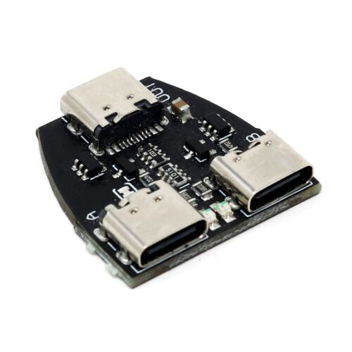
Power USB-C devices from two USB-C power sources! Where does power go? Power from each USB-C input (A/B) connector goes via a MOSFET “Ideal Diode” to the…
Read moreThis is a placeholder topic for “5V USB-C Dual Supply - Dual Ideal Diodes” comments.
Power USB-C devices from two USB-C power sources! Where does power go? Power from each USB-C input (A/B) connector goes via a MOSFET “Ideal Diode” to the…
Read moreWould you guys consider making a variation of this product, but with the voltage just a bit higher so you could power a pi 4 with it, that would be an awesome kit
Hi Patrick,
Good news, this unit will almost certainly work fine at 5.1V. 5.1V is within the USB spec for 5V, and the “Fixed at 5V 3A” comment is just saying it doesn’t support reporting as a lesser source/sink due to the pullup configuration. See the deep dive docs here:
https://www.st.com/resource/en/technical_article/dm00496853-overview-of-usb-type-c-and-power-delivery-technologies-stmicroelectronics.pdf
Hi Patrick
This looks like a variation of a classic “diode OR” supply configuration but using Mosfets instead of diodes. Mosfets have the advantage of lower forward voltage drop when switched hard on. You will never get more out of it than what you put in. In other words if you want a higher voltage out you need to put a higher voltage in.
If used as a load sharing set up both power supplies need to be exactly the same or very close. If not the higher voltage will supply all of the demand until the output voltage is forced to drop to the lower level when the lower supply will pick up some of the load. Under these conditions the higher voltage supply would be operating at something like maximum output all the time with only a little help from the other unit. Not an ideal situation with one supply possibly being over stressed and prone to failure. If they are both the same or very close the load sharing will be a lot closer. This is easier to achieve with adjustable supplies.
If used for redundancy both power supplies should be capable of providing the total load requirement. The higher voltage one will prevail but in the event of a failure or “brown out” of this supply the hot standby supply will be in use.
This device would be particularly useful where a device needs to be connected to and communicate with a computer where the computer USB port will not provide enough current. I see data is transferred to the output via input A. Connect your computer to this port then have another larger supply (to provide the required current) connected to input B. Make sure the supply connected to B is slightly higher voltage than A and this supply will provide all of the required current.
I note the term “ideal diode” used. Personally I don’t think this device exists but a hard on Mosfet will probably be as close as you will get. The “ideal” device is sometimes used in the initial simulation of an idea or concept and fine tuned later with a “real” device. In other words it is imaginary, like √-1.
I also note the absolute absence (that I can find anyway) of any specs or really useful information like some sort of circuit for this device so one could make some sort of decision re usefulness for a specific task. Sadly this seems to be the norm these days so personally I would tend to use a couple of schottky diodes (where information IS available) and allow for or put up with the bit of extra voltage drop. All the above comments would apply.
Cheers Bob
Hi Bob,
Thanks for sharing your insights, it is a shame the design is closed source for this product so we don’t have a full schematic.
I think a lot of newer battery management modules will now embed most of the features of this design into their products so you can have battery managers that have the battery ready to go for redundancy, but not continuously loaded down and burning through the battery life cycle by being fully loaded.
I am looking for a simple and inexpensive device that can automatically switch between two power sources with Power Delivery (PD) capabilities and output the power to a single device.
Would this work?
5V USB-C Dual Supply - Dual Ideal Diodes
Hi KwokKeung
If you want the output to communicate with BOTH sources to use Power Delivery. Then your question
I think the short answer is NO.
I base this on this line copied directly from the description text
Quote:
“Where does data go? USB 2.0 data from the USB-C port (A) is connected to the output USB-C connector.”
End quote
Which is part of the Core description.
Cheers Bob
Hi @KwokKeung298281 ,
Welcome to the forum!
Bobs response is spot on. Unfortunately, the 5V USB-C Dual Supply - Dual Ideal Diodes module won’t work if you need full Power Delivery (PD) negotiation from both inputs and on the output.
It’s designed for simple 5V-only power switching, not full USB-C PD negotiation (like 9V, 12V, 15V, etc).
Core Electronics doesn’t currently stock a ready-made module that can automatically switch between two USB-C PD sources and properly negotiate PD to a single output device. It’s a more complex requirement that usually involves a USB-C PD controller chip (such as TI’s TPS65988), and likely a custom or semi-custom solution.
Best of luck with your project!
Hi Ryan
I think you have the terminology a bit wrong here. This device does not actually “switch” as I understand from this…
Quote:
“Which power supply is used? It will draw power from the supply with the highest voltage and if the voltages equalize (due to the current draw) it will share the load on the power supplies connected to both USB-C connectors (droop method).”
End quote
This is copied straight out of Core product description.
As I stated a couple of years ago it is a bit hard to make a definite statement with the info available but it reads like a simple “diode OR” power sharing set up using Mosfets instead of diodes. Highest voltage wins. All my other statements previously still apply I think.
Cheers Bob
Hey @Robert93820
Thanks for the clarification, you’re absolutely right to point that out.
You’re correct that the module doesn’t perform active “switching” in the typical sense, and my wording there could’ve been more accurate. It’s more appropriate to describe it as a passive “OR-ing” setup using ideal diodes (or MOSFETs configured as such), where the highest voltage source takes priority and current can be shared when voltages equalise, as mentioned in the product description.
Appreciate you keeping the technical details on point, it’s always good to avoid terminology slip-ups, especially in power electronics. Your previous insights on the topic still stand strong.
OP wants to change between two power sources, which the device will do. The data connection can remain with source A, and is unaffected by the change in power from A to B. So AFAICT this should work just fine.
Hey @Jeff105671
You’re right that this device can “OR” between two power sources; however, it’s important to clarify that this board does not support USB Power Delivery (PD).
This means it cannot negotiate or provide PD voltages like 9V, 12V, or 20V. It’s strictly limited to fixed 5V at up to 3A, as it uses 5.1kΩ pull-down resistors on the CC lines to indicate a standard 5V sink, not a PD-capable device.
Bob,
Thank you for your response.
The device functions by directing power from either the solar panel or the charger to the camera, all through USB-C ports. There is no data communication taking place between the USB-C cable from the solar panel, the charger’s USB-C connection, and the camera.
Essentially, I’m looking for an automatic power switcher that can redirect the power source from a higher output to the camera when needed. For example, at night, when the solar panel stops producing power.
Sincerely,
K. Jay Chow
Please edit your post to remove the contact data.
The device you have selected will work just fine for that task while the camera is configured so that it requires only 5V. But, as noted, it will not support the PD feature of your adapter. If your power sources must support PD then the preferred arrangement is to have a single PD source and switch the supply to that source.
The situation where two devices (the PD adapter and the switch) are both trying to make decisions based on voltage and load, but using different criteria, will likely not be feasible and I doubt that you will find such a switch. A switch that can handle the higher voltage source for a single PD adapter will be a more reliable solution.
Would this device be suitable for delivering fast charging current to a smart phone, while having data go to an android auto head unit?
My head unit doesn’t supply enough current to keep the phone charged while on wired connection, and wireless has worked for me until a few days ago when I seem to be getting serious interference on the AA wifi causing audio stuttering.
Hey @Bonj, welcome to the forum glad to have you here,
This product is mostly used for simple 5V Switching between two devices, it doesn’t support full USB-C Power Delivery (PD) negotiation, which will put a serious hamper on fast charging attempts?
May I ask what head unit you’re currently using?
It is a generic Chinese android head unit. I’ve ordered one to test anyway and if it doesn’t work for this, I’ll find another use for it.
Awesome, @Bonj, let us know how it goes ![]()
It arrived today, but looks like it’s not going to do what I want. When I initially plug it in (data/pwr to head unit, pwr only to car charger), it gives my fast charging, but then it must negotiate charging with the head unit because it drops back down to slow charging again.
Back to the drawing board.
Shame about that @Bonj. But good on you for testing it. ![]()
And you can get our latest projects and tips straight away by following us on:
![]()
![]()
![]()
![]()