I’m just a simple hobbyist, learning as I go.
I bought this nice Adafruit DS3502 I2C Digital 10K Potentiometer from Core Electronics.
To test it out, I used the Adafruit_DS3502 library to set the wiper to position 0 for tenseconds then position 127 for ten seconds on loop. This should switch between its two extremes. Using a multimeter, i measured the resistance between the RW and RL pads.
The resistance certainly changes on schedule , but not between the values I expected . Instead the minimum was aprox 2kohms and the maximum was 12kohms.
I tried switching my multimeter probes around, so positive was on the RL pad and negative on RW. No difference .
I checked the resistance of just the multimeter probes and they are only 5-6 ohms.
So where does this additional 2kohms of resistance come from ? Have I understood how it should work? The product is advertised as having " 128 possible levels of resistance to choose, from 0-10K ohms" but is there usually a large margin of error ?
Any advice would be much appreciated. Thanks
2 Likes
Hi Mark.
I have never used one of these devices but I am suspicious when I see the CHANGE is the rated 10k, (2k to 12k). As if something else is going on. There is a voltage on the ohm meter leads when measuring resistance but I would not have thought that would affect the operation as after all in practice there is probably going to have all sorts of voltages present.
It is almost like you had 2k in series with the meter while measuring.
I noted that you switched leads around but did you try measuring from the other END of the pot to the variable point. There may be 2k built in to one end for safety reasons. The data sheet for the device may shed some light on this.
I had a quick look at that link but didn’t find anything that looked like a data sheet.
Cheers Bob
3 Likes
@Mark86044 Measuring the resistance may be fraught because the transistors inside the pot are relying on there being voltage difference present between RH and RL. A digital pot does not operate exactly like a variable resistor.
I’d be curious to see the outcome of a different test.
- Connect RH to +5V and RL to GND.
- Step the potentiometer 0, 63, 127 and measure the voltage between RW and GND at each setpoint.
You ought to see ~0V, ~2.5V and ~5V at the wiper. If so, the device is working as intended.
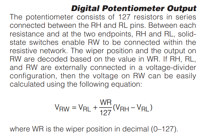
Further, you can also see in the datasheet the output is specified as the voltage at the wiper, not necessarily the resistances between wiper and RH or RL
In any case, best of luck with your experiments! Let us know how you travel.
DS3502 Datasheet
4 Likes
Thanks Bob and Michael for your suggestions. I just did a couple of quick experiments.
The resistance between RH and RW is the same as between RL and RW (approximately 2k-12k). But the resistance between RH and RL is always 10k!
I’ll do the voltage divider experiment but I suspect you’re right and that it’s working correctly to give a variable voltage and what I actually needed was some sort of programmable a variable resistor.
2 Likes
What is it that you’re trying to do - @Mark86044? What’s the project?
2 Likes