Hiya.
Got a wiring issue needing some assistance debugging.
Code
I’m using Thonny.
Running this code.
import neopixel
import machine

from PiicoDev_SSD1306 import *
from PiicoDev_Unified import sleep_ms


#Init Neopixel
np_pow = machine.Pin(11, machine.Pin.OUT)
np = machine.Pin(12, machine.Pin.OUT)
np_pow.value(1)
px = neopixel.NeoPixel(np, 1)

def pukPix(v):
    px[0] = (v, 0, v)
    px.write()
    sleep_ms(100)

def flickerNeopixel():
    for i in range(0,12):
        v = (i % 2) * 255
        pukPix(v)
    pukPix(0)

#Init Display
display = create_PiicoDev_SSD1306() #Onboard Neopixel flickers if you remove this line

while True:
    flickerNeopixel() #HERE I AM!
    sleep_ms(1000)
Files
I created and uploaded these files
- Download the PiicoDev Unified Library: PiicoDev_Unified.py (right-click, “save link as”).
- Download the device module: PiicoDev_SSD1306.py (right-click, “save link as”)
Lib install
Lastly I made sure my PC running thonny had Piicodev library.
pip install piicodev
pip show piicodev
Name: piicodev
Version: 1.10.0
Summary: Drivers for the PiicoDev ecosystem of sensors and modules
Home-page: https://github.com/CoreElectronics/CE-PiicoDev-PyPI
Author: Core Electronics
Author-email: production.inbox@coreelectronics.com.au
License: UNKNOWN
Location: C:\Users\optim\AppData\Local\Programs\Python\Python311\Lib\site-packages
Requires: smbus2
Required-by:
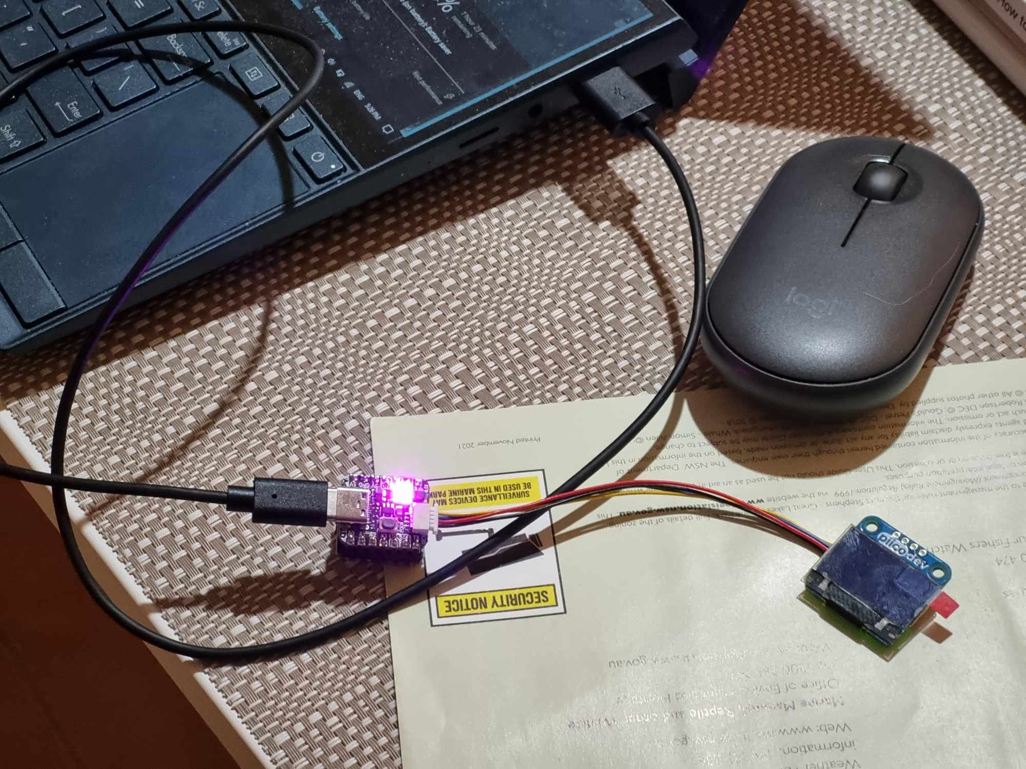
Setup Pic
Error
I’m getting the following error.
PiicoDev could not communicate with module at address 0x3C, check wiring
On this thread I noticed to check the addr pins are unsoldered.
mine seem to have a connection?
What does that mean? could that be the source of my problem?

Any other sanity checks to try?
Thanks champs. ![]()
Pix ![]()