I’m trying to fix a lab equipment issue, and I am relatively new to messing with electronics so sorry if I miss something basic We have a piece of lab equipment that measures pH, but the original pH probe (with a 4-pin connector) stopped working (photo attached). Now, I’m trying to connect a replacement pH probe that has a BNC connector(photo added) to the equipment’s pH port, which I think has 3 pins (photo attached—I might be miscounting, but it looks like 3 to me on the port).
What I know so far…:
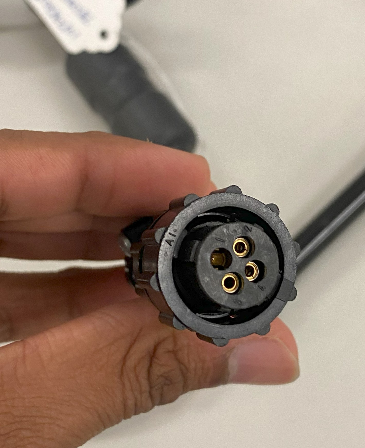
The original probe has a 4-pin connector, but it plugs into this 3-pin-looking port.
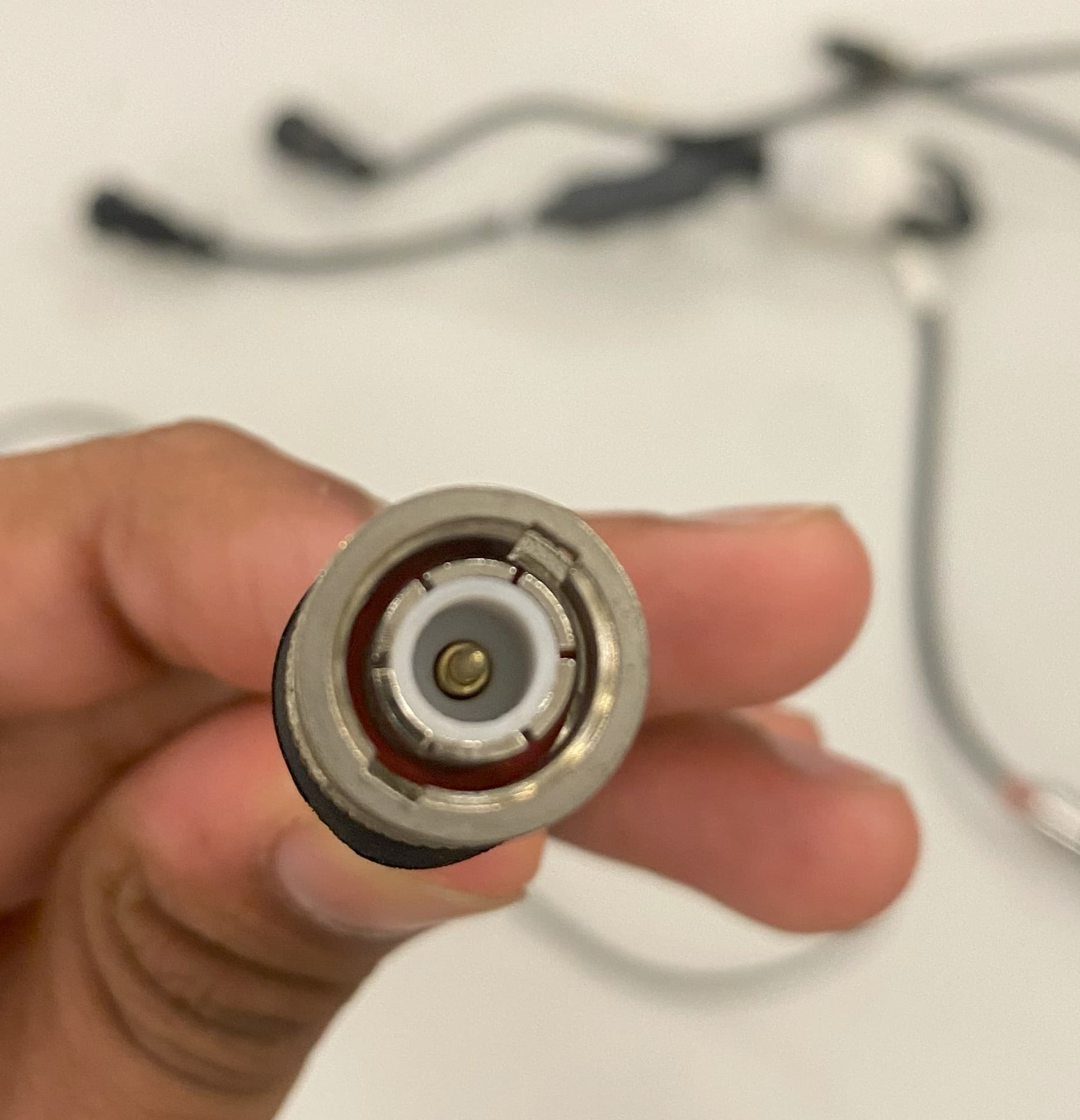
The new probe has a BNC connector (photo attached), which I understand is a coaxial cable with a pH signal on the center pin and shielding on the outer part.
I don’t have a pinout diagram for the pH port, but after some online research, I learned I should do a continuity test to figure out which pins are for the pH signal and ground. I can handle that part with a multimeter.
What I’m stuck on is what to do next. My questions are:
Continuity Test: Can someone explain how to do a continuity test on the pH port step-by-step to identify the signal and ground pins? I’ve got a multimeter but haven’t done this before.
Connecting the BNC: Once I know which pins are which, how do I hook up the BNC connector (signal + shield) to a 3-pin port? Is there an adapter I can buy, or do I need to solder something custom?
Risks: Since I’m new to this, am scared if I am going to fry the expensive equipment so any precautions?
I’ve attached photos of:
The malfunctioned 4-pin probe
The new BNC probe
The pH port on the equipment
Any step-by-step help or tips would be awesome. Thanks so much for your time!
Best,
Dennis
The BNC connector is coax: it is two pin - signal and ground. The 4-pin connector appears to be using three pins only. Co-ax is used for a very specific purpose, so it is unlikely that the replacement probe will be compatible with the old probe. If you provide full product details for the equipment and the new probe someone may be able to check if a connection will work.
To test continuity you will use either the ‘Ohms’ setting, to get a value reading where zero is continuity, or the buzzer/tone setting to get an audible indication that there is continuity.
Hi Dennis
Firstly welcome.
Well, that is certainly an unusual connector. The probe connector has 1 male pin and 3 sockets.
The instrument connector has nothing in pin 4 so assume that does nothing.
Professional audio protocol says the signal source (microphone etc) is male so if the protocol transfers this pin (1) will be signal.
This gives us a couple of possibilities.
It will be a fair bet that pin 1 will be signal or screen (being the odd one out).
If the PH measurement requires 2 wires it will probably be screen. If the measurement is one wire plus screen it could be either. I am assuming here that the cable will be screened. A continuity check with the multimeter will confirm this.
The new connector is indeed a BNC type and looks like is a single wire and screen for PH measurement.
Regarding question 2. You don’t. I have never seen this particular connector but I would think any sort of adaptor would be pretty scarce.
The only other way out would be to firstly determine if both sensors are compatible. If you are up to it you could cut the connectors off and re terminate the new sensor in the old connector. If the old sensor connector is moulded onto the cable this probably would not be possible or practical..
Questions. Us your skill level up to this sort of thing.
You don’t seem too conversant with multimeter use. I would suggest doing some serious research on this subject as anything beyond very bare basics I think would be a bit beyond a forum discussion.
In a nutshell the 2 connectors are like chalk and cheese. Even the connecting type. BNC has bayonet retaining system while the original looks to be a screw type. The co-axial equivalent type here could be TNC but the actual diameter looks different also.
Sorry for not being able to offer more help but I think this is going to be quite a difficult one without more knowledge of the measurement system.
Cheers Bob
Jeff’s reply overlapped. Fully agree, he has said the same sort of thing in a much shorter way
Check with a multimeter. Set your multimeter to the continuity mode (often looks like a diode symbol or soundwave icon).
Touch your multimeter probes together to make sure it beeps. (That’s a working continuity check.)
Identify the ground first:
Touch one probe to a known grounded part of the equipment (for example, the outer metal case if it’s metal).
Touch the other probe to each of the 3 pins in the pH port, one at a time.
If it beeps, that pin is ground.
The switch position will show these icons. The screen will show the one selected.
You need to select Continuity mode first. The screen should display the “sound” icon. The DMM will beep when a resistance below a certain figure is detected. This could be something like up to 50Ω. Alternatively an actual resistance could be observed. This is probably the default function when this selected with the switch. Be aware the DMM probe leads will have a small resistance which will show up here. You will never read zero Ω.
A read of the user manual should explain all this, possibly with little diagrams.
I think Dennis maybe should read this before venturing any further. If he hasn’t got a copy I am sure that if he looked up the make and model he would find one. A study of this could explain things a lot easier than trying to do some sort of DMM course here. I believe I suggested some research above.
Cheers Bob