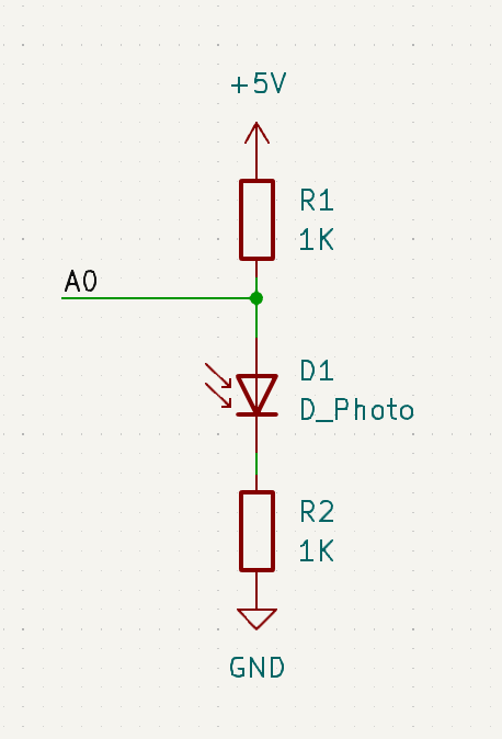
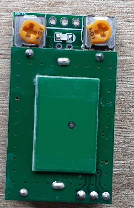
Have constructed a simple IR proximity sensing circuit. IR LED and IR sensor LED about 2cm away from each other. Based on this project.
I poll the analog input value and log to the serial console every 100ms. When nothing is near the sensors, the analog input reads 15-30. When I put my hand near the sensors, it rises up to around 60 for a little under a second before dropping to about 8 for a couple more seconds then rising again. It keeps doing this.
Could you shoot us a link to the sensor you bought?
Also, I’m not sure that project will work? Someone more versed in the analog domain can correct me here, but light is opening a current path between the ADC pin and GND, and the ADC pin is just set up as a floating high-impedance input, it’s not referenced to anything.
Try with and without R2, I’m not sure if a divider or open drain arrangement is best. Generally photodiodes are very “on-off” rather than analog, but that seems to be the goal of a project.
Yes, my goal is very much “on/off”. As can be seen from my other post, I’m looking for a robust way to detect the presence or absence of a model train.
I had just bought raw components, but it looks like it would be only marginally more expensive to buy pre-fabbed proximity or break beam detectors. That’s more a topic for the other post - this one is just about understanding how to build a raw IR detection circuit.
Given that I only care about on/off, is it possible to build this circuit using a digital pin, or am I still better to sample an analogue pin and use a threshold?
Without a threshold potentiometer, I’d still do it analog for now and see how it behaves. You can always move to a digital pin later since you’re in the experimentation phase
Hi James
The top circuit would not work. The RX photo transistor is the wrong way around. Being NPN the emitter should be grounded NOT the collector. The whole set up is upside down.
Cheers Bob
So, I wired the IR LED: +5v → 220 Ohm → LED (anode - cathode) → GND
And I then wired the IR photodiode: +5v → IR photodiode (cathode - anode) → (A1 tap) → 200 Ohm → GND, on it’s own little PCB.
It’s pretty jittery, but now if I have the detector sitting off by itself A1 reads around 6-10 (any shadow nearby can cause a small spike) but if I hold it directly above (and facing) the IR LED I read high 300s (with some jitter). So in that sense it’s working.
I’ve ordered some break beam and proximity sensors from CoreElectronics so I’ll try them out soon and see how they work.
Hi Andrew
Be a little careful here. That connection of +5V to the PHOTODIODE cathode is all good if you want a switch as I think you do.
But that link to the Jaycar product you posted earlier is a PHOTOTRANSISTOR which is a bit different. In that case I believe the +ve side should connect to Anode and the transistor should turn ON.
The 2 devices, Photodiode and Phototransistor are different so you need to know which you are using.
I could be wrong here as it is a long time since I had anything to do with this sort of thing but I don’t think so.
Cheers Bob
Hi Andrew
Attached a quick sketch showing the photodiode and phototransistor connections and orientation.
Either one could be used as a receiver but you have to know as the polarity is different.
I have shown a schottky diode (used because of lower forward voltage drop) feeding the Arduino digital input with a “common” pull down. I have done this as I am aware of your other post re model trains. You can form a group and connect all the group diodes to the common pull down and Arduino input.
As it stands the point “X” and Arduino input will go HIGH when (in the case of a group) one or more beam is broken and the transistor / diode is OFF. LOW in all other circumstances.
For your interest this configuration is known as “Diode OR”.
Cheers Bob
You are correct - it is indeed an NPN phototransistor and not a photodiode. That is helpful when researching how to use it.
So, according to the data sheet, the short leg is the collector and the long leg is the emitter. So by chance I actually wired it up as shown here, except with a 200 Ohm resistor rather than a 10k Ohm resistor.
One thing I didn’t notice previously is that the data sheet recommends pairing it with this lamp, which is not the one that I am using.
You might have damaged the transistor. The spec says ON current is 0.5mA hence the 10k (I nominated 5k1 without looking at spec sheet as I did not know what you are using), Use 10k. Your 200Ω resistor would allow 25mA which might have been too much. Don’t use it and confuse yourself, use a new one and discard this one.
The load resistor can be in either collector or emitter circuit but the operation will invert, LOW instead of HIGH when beam broken. Use the arrangement I sketched, load (10k) in collector circuit. This makes the use of several detectors on a single Arduino doable with the “diode OR” arrangement I sketched. Increase the common pull down resistor to 100k minimum. This pull down is required as the diodes will prevent the pin being pulled low and it will float. This resistor will form the bottom leg of a voltage divider with the 10k load resistor and if too low the voltage on the Arduino pin will not be enough to switch. If you have trouble here increase this to 200k.
The main difference is physical size (5mm against 3mm dia) they both operate at 940nm.
Cheers Bob


