This is a placeholder topic for “Artech Digital Multimeter - A5030” comments.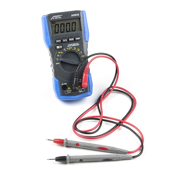
You can use the multimeter to measure DC and AC voltage, DC and AC current, resistance, continuity, capacitance, frequency, and test diodes…
Read more
Hi, does the Artech Digital Multimeter - A5030 come with the probes shown in the picture or do they need to be purchased separately? Thanks.
2 Likes
Yes, It comes with probes. I have bought one recently, you only need two AA battery.
2 Likes
From the product description
“You can use the multimeter to measure AC/DC voltage, AC/DC current, resistance, continuity, capacitance, frequency, temperature, EF, Hz DUTY, and test diodes.”
I have lot’s of questions.
- What is EF?
- Hz Duty? as in I can measure the frequency of a DC/AC waveform?
- What is the difference between Frequency & Hz Duty Cycle?
- Test diodes? What would I be testing? It’s limits?
- Temperature? Like… in Celsius?
Thanks in advance.
Pix ![]()
1 Like
Hi Pix,
Great questions!
I got GPT’s answer:

And Google found me this great video:

I imagine that its similar to this function on a Fluke multimeter: How to Measure Duty Cycle with a Digital Multimeter | Fluke
Pretty much, you can test the forward voltage of them: How to Test Diodes with a Digital Multimeter | Fluke
Yeah! There’s a K-type thermocouple included so could say… strap it to an IC with some kapton tape to see how hot it gets.
Any more questions or queries send em through!
Liam
1 Like
Hi Pix
“Hz” IS the frequency as in kHz, MHz etc. "Duty cycle is the ratio between HIGH and OOW time of a repetitive square or rectangular wave (a square wave would be 50% duty cycle).
You can’t test the reverse and forward resistance of a diode with a DMM resistance ranges. There is not enough voltage at the probes to turn the diode on. The same applies for transistor junction. To overcome this the “diode” test is available where the voltage in increased with a controlled amount of current limit. What is displayed on screen is then the forward voltage drop of the diode (Volts) with the reverse showing overload or infinity (good diode). LEDs can be tested this way also as there is usually enough current to illuminate dimly and you can see the different forward voltage drops with different colours.
Yes you can measure the frequency of an AC waveform and will display in Hz or multiples of up to a limit, usually quoted in the specs.
DC has no frequency.
Yes. Usually defaults to Celsius but some are able to change to Fahrenheit. With a K type thermocouple usually supplied with plugs for the meter.
One little quirk to this. If you short the DMM inputs (Common and hot lead) and switch to Temp measurement you will see displayed the ambient temperature inside the meter. That is because the electronics are compensating for a “cold junction” that does not exist without a thermocouple probe connected. “Cold Junction”, that is another subject altogether and if you want to know all about it I would suggest Wikipedia or similar.
Cheers Bob
I agree! ![]()
I’m confused because the product description has two modes.
- Frequency
- Hz duty
What would it mean for the duty cycle to be measured in hz?
So we’re on the same page, I’ve tracked down this desmos graph of a square wave where …
- f is the frequency
- A is the duty cycle.
Are we saying the “hz duty” mode coresponds to A??
But it expresses duty with the unit hz?
Pix ![]()
1 Like
Oh… there is a datasheet on the product page 
Ok so I’ve read the datasheet and I’ve learned that the multi-meter dial can move to HZ / DUTY mode.
I think the datasheet implies that, in this mode, the meter will measure EITHER frequency in hz OR duty as a percentage.
@Liam maybe a clearer product description might look something like (??)
“You can use the multimeter to measure AC/DC voltage, AC/DC current, resistance, continuity, capacitance, frequency, duty, temperature, EF, and test diodes.”
Pix ![]()
1 Like
Hi Pix
Just looked at that link.
“f” seems to represent something. By the look of the graph it is in units of something could be second, mSecs or µSecs. For illustration it does not matter.
“A” represents Duty Cycle. Expressed as a decimal part of the whole which is 64 somethings. It is quoted as 0.8 which is clearly the 0.8 of the total cycle time the signal is HIGH. I suppose duty cycle could be expressed this way but it probably more common to have said 80% which is the same.
This is a bit misleading as “f” is normally used to represent frequency, in this case it appears not to be.
Cheers Bob
PS there is a lot of information usually in data sheets. Always wise to have a read before branching out with a lot of confusing queries. Also helps understand your instrument and its use.
2 Likes
Hi Pix and Bob,
Great dive into the nitty gritty - I’ve updated the product page with the reword so hopefully its a bit clearer in future!
Liam
2 Likes
Hi.
I know that you can use the diode function of a multimeter to test an LED and determine the Anode and Cathode. I get the voltage drop, in must cases ~1v and the LED is very dimly lit.
Given that the LED lights up a little when I do this I assume the probes are live… ![]()
Is this multi meter ever going to hit high voltage? Are the probes dangerous in this mode?
Hi Pix,
There is a maximum.

There isn’t a standard to what a mulitmeter can do but from what I read 3.2V is on the higher end for a hobbyist.
1 Like
Hi Pix
With the modern DMM in the resistance ranges the voltage at the probes will not be enough to turn on a PN junction so you can often measure resistors in circuit. This is to protect the fragile inputs of most ICs and other solid state devices. In the days of the old AVO meter the first thing you had to do was to remove the 22.5V battery (used for higher resistance ranges) in case of accidents when making continuity checks.
In the diode check range the probes have a constant current supply connected I think 1.0mA with a voltage enough to turn on a PN junction (0.7V). Open circuit (no current) this would probably measure the full (9V) battery voltage. I am not sure and have never bothered to measure it. When this 1.0mA is applied to a forward biased diode junction the voltage drop is measured across the junction and displayed. The glimmer in the LED is the result of the LED passing this 1.0mA so is a reasonable check of a LED as well as identifying the lead polarity. That is of course assuming the leads are correctly plugged into the meter.
Could I think get to the 9V of the battery and as such could be dangerous to some devices if applied between ground and said device. Would probably be worth checking just what the open circuit voltage is in this mode. I think I have another working meter so might just do that.
Incidentally this is not confined to his particular meter, most DMMs are the same.
Cheers Bob
Just checked.
One meter measures an open circuit voltage of 3.24V and reversing the situation the other measures 3.26 so I would think the nominal open circuit voltage would be 3.25V so that should be OK for most situations. The exact voltage should not matter as long as the constant current (I think 1.0mA) is accurate.
2 Likes
Thanks @Robert93820 and @Jack
Sounds like there are some things I need to watch out for in-case I damage active components.
The good news is the voltages seems safe for humans so I’ll be around to throw my broken ICs in the bin. ![]()
Pix ![]()
Shouldn’t break too many ICs at that voltage.
Would never be harmful to humans unless you happened to grab them while connected to 240V mains or something like that.
Cheers Bob
I’ve been gifted a circuit board that has components I would be interested in de-soldering and keeping.
Unfortunately, the board contains 500v capacitors.
I’m completely uninterested in attempting to discharge them with a screwdriver and I don’t own a resistor with the kind of watts required to discharge safety.
I’d like to measure the voltage of the caps to see if it’s safe for me to interact with the board.
** I’m unsure if the probes that came with my multi meter (the A5030) are going to insulate me from 500v. **
Am I right to be worried or will the probes insulate me?
Those are some big capacitors you have there. I unfortunately can’t find any info on the provided probes. It may be worth looking at some other means of PPE in case things go awry.
1 Like
My survival instinct tells me that if it’s too dangerous for the multi-meter I’m simply not experienced enough to interact with them.
I know that the board has been disconnected for at least a month, and I can see discharging resistors on the circuit. Cold comfort though.
Hi All
Depends on what the capacitance is. If only a few pF you probably would not even feel anything even if they were fully charged which is highly unlikely.
The fact they are 500V does not mean they were ever used at that voltage. It just happens that NPOs and similar are rated to withstand 500V.
Most DMMs are rated overall (including probes) for 600V so that should not be a problem. I stress once again that if you are concerned find out or get some idea of what voltage the board worked at. The working voltage of any electrolytic should give a clue as for an electrolytic to function properly the actual voltage should be fairly close to the rated voltage.
A bit over the top. If Pix is that concerned he should leave it alone. Reading between the lines of this thread that might not be a bad idea anyway.
Cheers Bob
3 Likes

