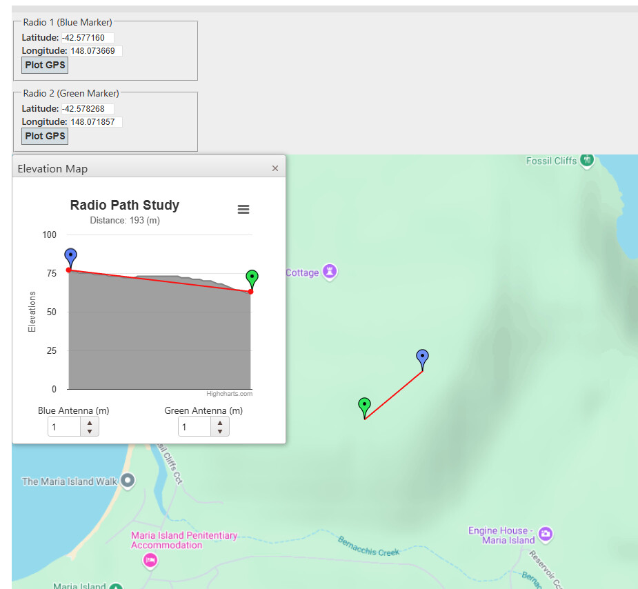
Hi, we recently conducted a pilot trial to test LoRa connections at Maria Island, Tasmania. We used Portenta H7 with LoRa Vision Shield with this 915 MHz uFL antenna. Below is the map of our deployment of 2 LoRa nodes ~200m away from the gateway.
We used the RAK7249 outdoor gateway with it’s antenna ~4m from ground (using an extender). The Portenta and antenna were inside a PVC pipe for weather protection. Unfortunately, connection was patchy and my guess is that maybe we need a better antenna.
Could you please advise on a (perhaps) better antenna for outdoor projects? Also, could somebody with outdoor rural LoRa experience help us figure out what other things we could do to increase LoRa connectivity?
Lora is mainly line of site (for distance). You may get some gain with outside antenna.
Line of site with a spread factor of 7 I have gotten 4Km, but a base station antenna at the base and a smaller 2db antenna on a portable unit. And based on the signal strength I am sure I could get a longer line of site coms; just not yet tested.
You could try increasing the spread factor, as a rule higher spread factor = longer distance at lower speeds.
Please note: I have not tested the gear you have to claim what I setup should be better, simply reporting on my experience.
As a rule Im not a fan of any antenna that is not 100% in the open air, so while the specs of you antenna (6db SWR < 1.5) sounds good, the fact its comes with a sticky back means you need to ensure you dont affect the signal based on what you stick it to. Also not sure I full trust the swr over such a wide range.
Any chance of photos of the setups ?
Thanks for your inputs, @Michael99645! Your experience is very helpful for me to learn and make different mistakes so I really appreciate it
I’m sure you must have imagined how challenging it must be to achieve line of sight in rural Australia, especially Tasmania. We def did not have line of sight in our experiment and the end node were ~50 cm above ground.
Sorry, I can’t share any picture of the setup yet as we plan on publishing results from the prototype I can help you visualise it better perhaps: Portenta + Vision Shield with said antenna attached and 4S1P Li-ion battery powering Portenta inside a closed PVC stormwater pipe.
Maria Island (like other places in Tassie) has Possums and Tasmanian devils that can gnaw on the node’s antenna hence we had to put it inside a PVC tube for the experiment. Thanks for sharing the 1/2 Wave 2dBi antenna, though I’m still concerned for the same. Even if I put the antenna you suggested outside the PVC shell, I might have to reinforce it with something else to ensure it doesn’t get chewed by a wild animal.
Another thing I’d like to add is that we were using adaptive data rate during the test. I later realised that maybe I should fix it to DR0 for a better spreading factor based on this document by RAK. I am just getting started in the world of RF and LoRa so was wondering if you could help me clarify: is DR set on the gateway side or end node side? I have tried reconfiguring on Portenta but it always goes to DR2 on it’s own, which makes me wonder.
Radio can be a bit hard sometimes as different frequencies can have different challenges.
Also as a rule “you cant make something from nothing”, so when you see an antenna with “gain” it will come from somewhere. so getting a radiation pattern for an antenna helps, but always easy to find. e.g. the more gain them smaller the angle (and/or direction) the antenna will work in.
So if all nodes are fixed, some form of directional may work better.
From memory my non-line of site test had some houses and dirt between my portable unit and base, and I got about 300m depending on exactly where I was. So it could work.
Not sure on your exact units, but if you can extract the SNR that can help with your tests. i.e. with the stick-back antenna you have does it work better or worse of you rotate it a little; i.e. it may have a “better forward face”.
Again this may or may not help, but I have been keen to run a test one day… I wonder if a ground spike would help.
Without a deep dive into radiation patterns, is would tend to try to “point” antenna’s at each other.
With a stock omni directional antenna it should radiate in all directions equal. But the only bit that matters is the bit that hits the other antenna. If you consider the following, with two radios, One with a green pattern and one with a red pattern (as seen side on). If the antenna is up/down and you pattern is too narrow, then it may miss the other radio (or be weaker then it should be).
Hi Prithul271176
900MHz is about the frequency area that is used for “tropposcatter” systems. As the name implies this range readily “scatters” around objects, over ridges and the horizon.
You say you are not line of sight so it is quite possible you are having an unwanted “scatter” signal arriving out of phase with the “wanted” signal causing partial or complete cancellation on a random basis. If 2 signals of nearly same strength arrive 180º out of phase the end result will be nothing. Without walking the path with a suitable spectrum analyser anything I say would be a complete guess.
If it is possible I would suggest trying 433MHz. It may be a better choice for your application.
Or if a scatter signal is strong enough you might be able to use it. You would need directional antennas and aim them at the edge of suspect obstruction to gather the scatter signal instead of trying for a direct signal. I am afraid only experimenting will give you the answer.
Another more exotic move would be to use a repeater to get around any obstruction although this may not be very practical. Works better if you can have a frequency change but without this any gain has to be less thatn the front to back ratio of the antennas or you will have “sing around” in a big way. Don’t forget any “scatter” system will be still there and the object without a frequency change is to provide a wanted signal strong enough to overpower the unwanted one.
Cheers Bob
Just thinking about this. Is the trouble you are having that you don’t always get a message sent ?
Using lorawan, you normally set the channels you use (a subset of the available) to use. The Gateway then attempts to scan that subset and expects the client/node to send on one of those channels.
When testing I would ensure the node is limit to using just one channel that you know the gateway should hear it on.
i.e. I have seen nodes that by default tend to enable all channels but the gateway will be a smaller range. this increases the chance that the node will send on a channel that the gateway will never attempt to listen on.
I am assuming that since you are using a gateway and nodes you are using loraWan and that there is an internet server somewhere that expects to get the packets. Double check all the settings to ensure they match. e.g. in loraWAN there are thee main modes, the default being A, where the node will send data, go to sleep, wakeup at a fixed time later to listen for a response on the return channel. Normally if this is an issue, your server will get the data, but the node wont get any ack (if enabled).
Hi Michael, no, the trouble has been in establishing connection in the first place.
Thanks for the suggestion. I will try this out now.
Yep. When we setup the gateway, we look for a 4G/5G rich spot. We’re on Telstra and they’ve got Tasmania covered pretty well (except certain parts of west island).
I took care of this bit before the field test but I will check again. I did it pretty early on but had to switch from AU915 to AS920 since Arduino Portenta does not support AU915. Cannot recall if I double checked settings afterwards.
Be careful with that. The key difference is frequencies allowed and may have some minor different re power output and talk time. So while you selected that make sure to stick to the AU915 Channels.
I assume you tried this “on the bench” first and it was working ok, then had issues in the field ?
Hi Prithul271176
I just had a closer look at your aerial pic. If you think you have a signal strength problem you may have to do some sleuthing.
That pic looks like a Google earth effort. If so if you draw a line between the gateway and each camera site from the EXACT positions Google will give you a path profile which might provide some clues. This will be a “flat earth” profile but because the distance is small earth curvature can be ignored I think. This will be “ground level” so you will have to add in the trees (to scale). I note that one of your cameras seems to be buried among the trees. This may or may not be a problem but is something you can do without if you can.
Does any of this equipment provide an RF signal strength indication. If so you might have to set up a mobile situation you can carry and walk around a bit. Even walk the path with your measuring set up noting what happens re signal level. To make any sort of sense out of such an exercise you need to use these figures, don’t just rely on an “if it works or doesn’t” system. That will tell you nothing that you don’t already know. It doesn’t work as expected.
These numbers don’t have to be actual signal levels like µV or dbm but comparisons will be useful starting from just a few metres away from the gateway. Your equipment might just provide a number as an “SSID” output. That would do.
Cheers Bob
Yeah, we could not find another bald patch of land around the place to set Cam 19. This is practically one of our biggest challenges too.
No, but we have now planned on using a field tester (like this one by RAK) to get this info. It could also be a good experiment to find whether it’s a node or an antenna issue.
You click on the icon “add path”. Give the path a name in pop up box and create and save it.
Place the cursor on the path and right click it.
Select “Show elevation profile” in drop down box.
Profile and all info at bottom of your screen. There is a cursor you can move along and the Google Earth Pic shows the position on path line.
The best idea I have heard yet. Basically a hand held field strength meter dedicated to this use. If you intend playing around a lot more you will find this a most valuable tool.
You are doing what I suggested above using any SSID indicator available only with a much better and easier instrument.
About the only way you are going to find out without an awful lot of really Flying Blind experimenting.
Good thinking
Cheers Bob
Add on: Michael99645 reply slipped in while I was composing mine.
I don’t know where Michael99645 got his positions from but if he is correct you DO have a line of sight problem. The Google earth profile will be a good check. I am not sure but I think that site does take into account earth bulge and corrects for 4/3 earth radius.
Oh this could be super useful to me, Michael! Thanks a ton for sharing
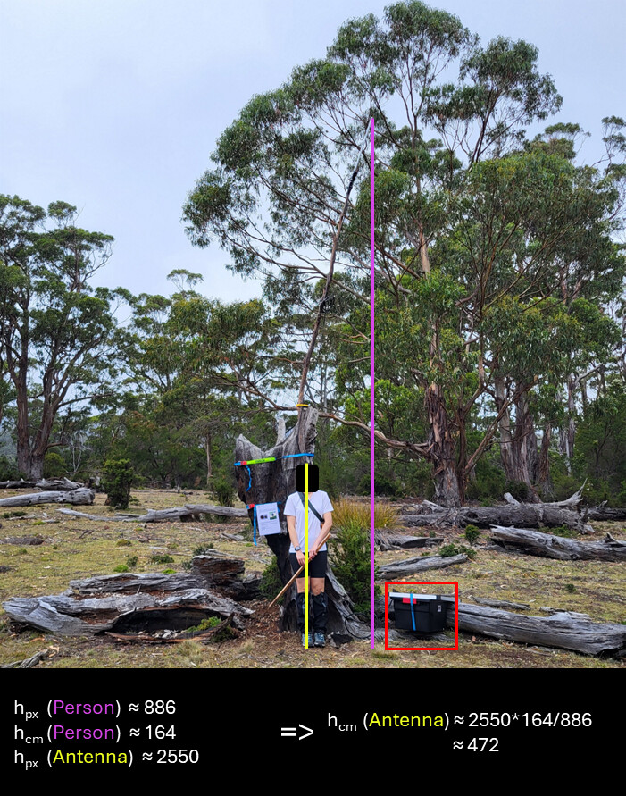
Will do, thanks for the suggestion. We took a 6m long extender with us and found the longest fallen branch to attach and host the antenna. We were lucky to find a long one but cannot always count on luck. GW setup pic below, hope you find it interesting! The red annotation indicates the box in which we kept the battery, inverter and the gateway.
Hi Prithul271176
A Google Earth profile would be a good check.
A reason why I recommended the check. You can zoom Google earth and put the path ends exactly where you know them to be.
If your RF source is down the bottom and the antenna at the top you have another consideration. Cable loss. This will depend on the cable quality and length and could easily burn up half your available power and if coupled to an iffy path and not much power in the first place the problem increases in proportion.
If you can physically see the antennas along one path the problem could still be out of phase echo signals. There is another which I have been staying away from it is called the “Freznell Zone” which you should stay clear of. It is the zone where an echo or reflected signal will arrive at the receiver 180º out of phase with the incident signal. In other words the physical path is one half wavelength longer than the incident via the reflecting path. The echo path could even be flat ground in which case antenna selection is looked at.
I know all this is confusing but if your problem is signal strength these thing are unfortunately a fact of life and will contribute in one way or another.
Many years ago when doing 500MHz radio surveys we carried out a “height gain” test where the antenna was lowered in 5 foot (pre decimal) increments and the strength measured. Sometimes the signal strength would increase. This would indicate some sort of echo signal influencing the incident and further investigation warranted.
And yes. RF and antenna propagation is something of a black art.
Cheers Bob
Just to add to Bob’s comment, double check ALL connectors. SMA has every combination you can think off, as such I have seen people join a bit of coax, but the coax was a different connecter (RP). If you get two with the pin, thats easy as they wont screw together. BUT if you get two without the pin, they will screw together but not make contact.
As for my maps, that was just a quick best effort based on your image, so I could have been off. The radio line of site check sites are good as you can add your antenna height as apposed to just ground level.
I had a quick look at the test device, it looks like it attempts to connect to your online server as a node, as such will need to support your setup as a node (So check the info on their site to make sure it will work with your setup.