How do I wire this up as the datasheet doesn’t mention the pin out (relative to the package) & there is no implied ground or power pins.
I’m planning on using an Arduino & 74HC595 shift register to set the segments & only require the ability to set all the segments to the same colour. I need to be able to set the RGB colour value dynamically. It woud be helpfull if you could point me at any projects using this product.
I already know about using 74HC595 to light up the segments & I’ve gotten these working with 4 separate red 7 segment common cathode displays with the following circuit.
I have the following issues which need clarification.
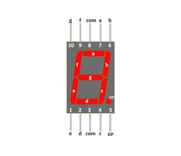
- My issues are the pin outs as these aren’t documented. Is it similar to a normal 7 segment led? Obviously it will 1-7 at the bottom & 8 to 14 on top.
- Can you please confirm if this product is common cathode as I’m wanting to use the anode to change the brightness?
- I think I can use separate WS8211 chips to handle the RGB lines for each segment. Is there an issues with only a single resister value for each RGB line? Red needs to be limited to 2.0-2.4V, Green to 2.85-3.4V & Blue to 2.95-3.4V. For my circuit I’m using a separate resistor for each segment so the segments are the same brightness.
- Are there any projects or circuits created using this product. I have been unable to find anything.
typically common cathode is preferred…or mostly used…if the negative rail is going to the cathodes i think…that is more common…
The datasheet on the SparkFun website most definitely shows the pinouts of the display. You don’t need a +ve and -ve pin as the control circuitry sets the voltage on each individual colour segment.
If you think of this display as a red display, a blue display, and a green display then you can set up one of them using your circuitry. When you have say the red working, you duplicate the circuitry and code for the green and blue. Then add code to handle what mix of RGB you want.
Here’s a link to the SparkFun page. Read the comments at the end.
Thank you for your answer.
Yes both datasheets mentions the pinout & their purpose. Which I now understand & am pretty sure it’s common cathode.
The pinout isn’t documented relative to the package. It mentions each pin & what it does. A standard 7 segment display has pins 1 - 5 at the bottom if you’re facing the front of the segment & go from 5 - 10 at the top in an anti-clockwise orientation. Is this package the same? If it’s not, then what is the pinout relative to the package?
The url shows what I mean https://components101.com/sites/default/files/component_pin/7-segment-display-pin-diagr_0.png
It’s a 7 dollar part & if I apply voltage to the wrong pins then I’m going to destroy the part or the segment.
have you tried contacting sparkfun for a more detailed breakdown of the specific connections on the display…???
I did get conformation that these are common cathode & am also trying Sparkfun’s support.I’ll return any useful information that I obtain.
Thankyou to all that replied!
Sorry to Resurrect this topic but if a picture showing the layout of pins not only would it help in knowing how to connect and what other parts I will need to use this in a project.
Hi Kiera.
Just had a look at the data sheet. You are correct in saying it would be a help if a pic identified the pins. Now I don’t profess to know a great deal about this device but the first thing to do is to identify pin 1. Looking at the base of the device (the pin side) with the device vertical the pins will number clockwise from pin 1 (assuming it follows “normal” IC pin numbering) so the only possibilities will be the pins at top right and bottom left as you see it. I would be very surprised if you can’t find some identification near one of these pins somewhere on the device indicating pin 1. It could be a dot or a bit of a chamfer on the corner but I feel something will be there.
Cheers Bob
1 Like
I have a 4 digit and a 1 digit 7 segment display.
Attached pics show the pin 1 (top right) & pin 16/10 (top left), label on the board.
(bit hard to see from my pics, but they are there)
The Sparkfun data sheet shows common anode for the Dual 7-seg RGB.
The two I have a single colour LED and have very different pinouts. An internet search allowed me to find the data sheets and hence the pinouts. One is common cathode the other common anode. I would test this using 5V through a resistor to the LED pins.
Suggest an internet search on how to connect a micro and make numbers display. Because of the wide variety in pinouts it is impossible to make a tutorial that would suit every possible display. But you can use the examples to determine how to use the particular display you have. I highly recommend using a display with a I2C interface, all the hard work is done in a chip on the display.
Cheers
Jim
2 Likes
Hi James.
These pins are pretty clearly marked. If the dual display is just as clear I don’t see what the problem is. If they are not marked (which I can’t imagine) in some way then yes, there is a problem.
Cheers Bob
2 Likes
There are no clear makings and forthat reason I want to check that nothing will be damaged if I try to wire it wrong so I can experiment with. Also with my limited knowledge of electronics I don’t see how to if possible to have 2+ different colours on the same digit. I have some ideas that trick the eyes while using a microcontroler board. Is it possible to set each segment to a different colour?(without using any logic or timing circuitry?
Can you provide a pic of the Display, it might help.
If the display is LEDs, they are like diodes and can be reverse biased, the main consideration would be to have a resistor in series to limit the current. 5V supply, 1K ohm resistor, 5mA current. LED would light up enough to see and not be damaged.
Looking at the schematic link provided by @Robin57159, you are correct. Each digit would have the same colour on each segment.
The answer is no, for the device in the link. From my knowledge of 7 segment display there are none that have a different colour for each segment. It would require too many pins and given the huge variety of dot & colour LCD displays, probably be no customer demand for it.
Regards
Jim


