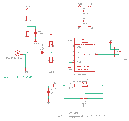
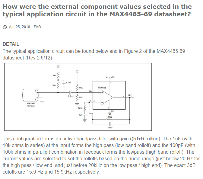
I have one of the Adafruit electret preams, and I am trying to modify this circuit to better suit my application.
I will be running my circuit with a regulated 5v supply.
So far I have increased the value of R2 to increase the gain of the microphone as I have the headroom available by using the 5v supply. I have also increased the value of R7 to increase the gain as my audio is far away from the mic.
Next, what I wanted to do was raise the low pass frequency as I am really only interested in voice band, not the whole audible spectrum.
This is where the confusion began because I am not sure that the formula for Gain and Low Pass shown on the Adafruit Schematic (hopefully attached below) is correct? and also, I am not sure how R5 & C4 are affecting the audio signal?
I am hoping someone can help explain the function/effect that R5, R7, VR1 & C3, C4 have on the audio signal. And also confirm the formula provided on the schematic.
Cheers!
Hey Ian,
Just letting you know I have seen this, it may take me a while to do the analysis but I am on it.
Hi Clinton,
I’m not sure how you went with this, but I’m pretty sure I have it worked out.
I was getting bogged down by the apparent complexity of the circuit, and forgetting what a basic non-inverting amplifier looks like.
Let me know if you think I’m wrong:
Essentially, to low frequency signals, the amplifier is unity gain. When the frequency rises, the reactance of C4 starts to fall and the R5 & C4 network starts to conduct and allow higher frequencies to be amplified in the usual manner, i.e. (Rf/Rin).
It looks like a high pass but that is because it is. Allowing the signal above your cut off frequency to go to ground, amplifies your output.
The low pass for your High frequency cut off is the VR1+R7 & C3 network.
As the frequency rises, the reactance of C3 reduces. When the reactance of C3 falls below the resistance of VR1+R7, you have reached your 3dB rolloff and the frequencies above that start to be presented to the amplifier in a unity gain manner. The higher the frequency gets, the reactance of C3 falls which reduces the gain of those frequencies.
Cheers,
Ian.
Yeah, that seems about right. I have been trying to get the full analysis done on this but i have had a very busy few days. Are you familiar with the software LTspice?
These are the filters as far as i can tell the high pass I am missing some larger interaction. But you you want I can upload the LTSpice file and you and simulate it yourself and have a play.


