My question involves a combination of electronics and electrics.
I am seeking assistance with regard to solving a magneto problem on a 5HP 4-stroke Briggs and Stratton petrol engine on a mulching machine. The magneto itself is very like the magnetos used on lawn mowers. When engines like this are difficult to start because of a weak spark, it is commonly recommended to just replace the magneto unit.
My machine has just such a problem, but I doubt that the real problem is in the primary or secondary coils. I think that the problem is in the electronic timing trigger circuit, which performs the function which formerly required the use of contact breaker points and a condenser. In circumstances like this I am hopeful that the magneto unit could be repaired rather than replaced.
Because the primary and secondary coils in a magneto effectively constitute a transformer, I have performed a test in which the magneto was mounted on a wooden test-bed, and the high tension (spark plug) lead was connected to an electrode mounted near to another (earthed) electrode. I connected a 12volt supply (from a battery charger) to the primary coil, but with the electronic ignition trigger circuit disconnected, and good sparks were produced at the electrodes. When the electronic ignition trigger circuit was reconnected, the sparking activity was very much reduced.
It is because of these test results that I suspect the trigger circuit device, which I understand uses a Darlington-pair of transistors. My knowledge of the electronics aspect of this problem is very limited.
I have a few questions about the design and function of this type of magneto.
- To what extent might its performance degrade with age, or as a result of its working in the hot environment of an air-cooled petrol engine?
- Does the permanent magnet (which is incorporated in the flywheel) degrade in strength to cause this problem? (In my case the magnet appears to be quite strong).
- What voltage is likely to be induced in the primary coil when the engine is running? (It would be helpful to know this so that an appropriate voltage can be applied in a bench test such as I described above.)
4 Likes
Hi Wilfred,
Have you got some photos, and/or a schematic? It’d make it a lot easier to follow along.
Do you just mean a basic points replacement circuit like this?
Have you checked your gap between the magneto rotor and coil? That’s usually the first port of call for weak spark. The gap should be as small as possible - a business card is usually about the right thickness to set the gap.
To answer your questions directly though:
- Yes they eventually get old and die from the heat, vibration, and intense magnetic fields. Engines are nasty places for electronics.
- No is the short answer. As above, check the clearance.
- Very hard to say - depends on a lot of variables. Maybe somewhere in the range of 10V-150V?
3 Likes
The operation of the coil in spark ignition should not be thought of as a transformer (although it is - sort of). What happens is (1) a current builds up in the primary coil, no current flows in the secondary coil (can’t jump the spark plug). This results in a slow build up of a magnetic field that encloses both the primary and secondary coil. (2) the current in the primary coil is stopped (points opened, transistor stops conducting, etc.). The magnetic field now has no current supporting it and has to collapse. To do this, it induces a voltage in both the primary and secondary coil (and this is where it can look like a transformer). If say the ratio of windings is 1:100, then the primary voltage could rise to 100V but is blocked by the open points/transistor, at the same time the secondary voltage rises to 10,000V, enough to create a spark and the magnetic field collapses creating a current through the plug.
This is the simple version, but it isn’t the whole story. In many ignition systems, there is a capacitor across the primary coil. When the points (or whatever) open, the capacitor and primary of the coil form a resonant circuit that stores some of the energy dumped by the magnetic field, with some going to the spark. Then the circuit resonates and dumps some energy from the capacitor into the coil and creates another spark. This can repeat a few times firing the plug and creating what looks like a ‘fat’ spark, but is several sparks in a row spaced microseconds apart.
Failure or degradation of the capacitor creates ‘thin’ sparks. This may be your problem. In a points system, the capacitor slows the build up of voltage in the coil as some of the energy is diverted temporarily to the capacitor. This is important because the points take some time to separate far enough that a spark doesn’t jump the points instead of the spark plug gap. This is not such a problem in an electronic circuit so the coil may be designed without a capacitor. However, if an electronic circuit is operated without a spark gap on the secondary (i.e. with the load to the plug not connected), then the voltage on the primary builds until the energy can go somewhere. Some electronic circuits don’t have provision to prevent this, and are destroyed or degraded. So good practice to always test an electronic circuit with a plug in circuit.
So in reply to point 3 of your questions, the primary voltage can be quite high, in the order of hundreds of volts when the spark fires. Which is why in an electronic circuit the device that interrupts the primary coil is a high voltage device. And there is not much point in finding that ratio, it won’t be very useful.
4 Likes
Hi Wilfred and all
The whole Briggs and Stratton engine is very much like the ones used on lawn mowers. There are a couple of items on Tube which suggest there is an electronic module available to directly replace the existing coil/points/capacitor system. I don’t think you even have to remove the actual points, just leave them there.
The whole coil/points/capacitor system used to be known as a “Kettering System” so I think if you wanted a detailed insight into the workings of this a Google search would provide much info.
Alan has provided a pretty good description of how all this works.
Cheers Bob
3 Likes
Thank you to the people who have responded to my call for help. I have tried to “think through this problem”, and have done some additional testing since I first wrote to this forum.
Oliver, yes I have fitted the magneto coil very closely to the flywheel, with a clearance of about 0.2mm. I would be happy to supply some photographs of this coil, but am not aware of how to attach photos to a comment on this forum. (Can someone please help me in this?)
Alan, your comments about the coil not really working as a transformer are informative. This machine was made (and labeled) as having “electronic ignition”. It does not use contact breaker points, or a condenser such as is used when contact breaker points are fitted.
I did have the idea to try and test the coil (before your reply appeared) by treating it as a transformer, by applying an intermittent 12 volts power supply across the primary coil terminals, and the secondary coil did produce electrical sparks in a spark plug when the electronic trigger module was not connected. When the trigger module was reconnected, there was very little spark activity when power was supplied to the primary coil. It is for this reason that I think that the actual primary and secondary coils may be properly functional, and that the real problem is in the electronic trigger module.
You made comment that an electronic circuit without a spark plug being connected might be damaged, but I wonder what method of testing you would recommend? As I understand it, any testing for the production of a spark would only be at low revs when the starter rope was pulled, and in any case a spark plug has an air gap which represents a high electrical resistance.
Thank you also to Robert for your comments, but as I explained above my machine has never had contact breaker points or condenser. Also, the actual procedure for fitting a coil is demonstrated well enough on several different Youtube videos. I am concerned to discover and learn more about how the electronic trigger mechanism works, and how to repair it, or to construct a replacement. It appears that this small device may not be available as a spare part.
It is because the coils seem to be functional that I am hoping to learn more about the trigger mechanism, which seems to have been designed as a device which could be attached to an older style coil. I would be happy to provide photos if I am able to find out how to attach them to my comments.
1 Like
Hi Wilfred,
Here’s how to upload a file…

Easy as that! 
PS. You should be able to pickup one of the ignition modules from a small engine specialist - like a lawn mower/garden equipment repair place, or you can often get them online from the likes of eBay. For example:
https://www.ebay.com.au/sch/i.html?&_nkw=briggs+stratton+5hp+ignition
1 Like
There is a good explanation of a magneto system without points (the Magnetron system) here.
Another link (which I can’t find again) talks about testing the coil. It says the coil may appear to test OK even if it has a broken wire internally. A typical resistance is a few thousand ohms. It also said the gap between flywheel and magneto is not critical up to about half a millimeter.
Regarding the testing - a spark plug gap is about 0.8mm and can be bridged by about 10,000V. In an engine it requires a bit more voltage because the mixture is compressed. If there is no plug attached and the gap between high tension lead and ground is large, voltages as high as 50,000V may be generated to create a spark. This creates an equivalent voltage in the primary coil and may cause a breakdown on the primary side instead of a spark from the secondary side. When the magnetic field collapses, the energy has to go somewhere - if not to the plug where it is supposed to go, it goes elsewhere.
2 Likes
Hi Wilfred
Sorry I missed the significance of that in your first post. Old age has well and truly crept up. Is your trigger unit separate from the coil. I thought most of this type of thing would be just 1 lump of black potting material with some iron laminations and a couple of wires sticking out of it.
Cheers Bob
3 Likes
May I say thank you again for the helpful comments which have been made so far. One of the reasons for my persistence with this enquiry is that I know that magneto problems are not rare, and I have seen that other people have had a problem very similar to the problem which I have had.
The Youtube video which was advised by Alan is very helpful in gaining a basic understanding of how the Electronic Ignition module works. I suppose that what I have been trying to find is how to test the electronic ignition circuit, or how to construct a replacement “gizmo”. One of the things which I find frustrating about this problem is that I have been quoted nearly $100 Australian for a replacement part. Another mower repair shop quoted $150. But I have found the identical electronic ignition magneto replacement kit in the USA for less than $30 (USA), or about one third of the price!! The problem is that postage costs from the USA would be quite high, and therefore not a particularly effective solution.
For the sake of completeness, I have checked the primary and secondary coils in my magneto with a multimeter. The windings of both coils are electrically isolated from the core of the magneto. The primary coil has a resistance of 1.1 ohms, and the secondary coil resistance is approximately 2.87K ohms. This leads me to believe (or hope!) that the coils are still functional.
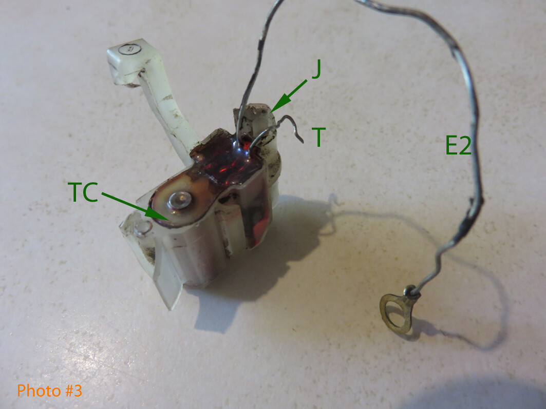
In the attached photographs I have labeled the most important parts, and the terminal connections, as follows:
E – Earth connection screw, which fastens the trigger-module earth wire, and the common leads for the primary and secondary coils to the core of the magneto.
E1 – Earth connection leads for Primary and Secondary coils (these are connected together).
E2 – Trigger-module earth connection lead.
H – High tension (spark-plug) lead.
J – Junction connector, for connecting the trigger lead, the primary coil lead, and the kill-switch lead.
K – Kill-switch lead.
P – Primary coil lead.
T – Trigger module lead.
TC – Trigger Coil.
3 Likes