Hi Liam, thanks for helping.
I’m attaching photos but the symptoms appear the same i.e.
-the usb cable is ok, I just downloaded one of the photos from my phone.
-the FTDI board’s Tx Rx leds flicker when testing with teraterm and ALSO Tx flickers when arduino is attempting to connect for programming.
- I’ve powered it with a 5V 2A plub pack.
-I powered up with IO 0 grounded, check photo.

Hope it’s clear for you,
Stephen.
3 Likes
Hi Stephen,
A few concerns about your setup
- Is the middle of the breadboard connected? I.e. power is being passed from the barrel jack to the jumper wires
- In your preparation you:
- Keep the ESP powered down
- Bridge IO0
- Power the ESP
- Try to program the ESP
- Remove the jumper from IO0
- Power cycle the ESP by removing power then reapplying it
2 Likes
Hi Liam,
I’m reading 5.16V at the ESP32 CAM 5v 7 Gnd pins via a RPi power supply.
I again followed your steps to power the ESP with IO 0 and Gnd shorted as per my previous photo but could not upload, getting fatal error message still.
Thanks for all your effort Liam.
I will contact via email.
Regards,
Stephen.
1 Like
Hi Liam.
I have again followed you instructions to the letter with the same ‘fatal error’ result.
I will now give up on the ESP32 CAM and look for another CAM combination.
I would like to return the ESP32 CAM boards and the FTDI board for credit.
How should I proceed?
Kind regards,
Stephen.
 | Liam120347
10 May |
Hi Stephen,
A few concerns about your setup
- Is the middle of the breadboard connected? I.e. power is being passed from the barrel jack to the jumper wires
- In your preparation you:
- Keep the ESP powered down
- Bridge IO0
- Power the ESP
- Try to program the ESP
- Remove the jumper from IO0
- Power cycle the ESP by removing power then reapplying it
1 Like
@Stephen25652 I am sorry the ESP32-CAM has not worked for you.
I bought an ESP32-CAM to mount on a robot cart I built for my grandson. This I have done, see pics, and am happy with how it works. The programming is as shown in my previous post and worked loading some Web Camera software I found on the internet. The pic of the cart & controller shows an old phone with the streaming video from the camera.
The LiPo will power the camera for about 1.5 hours, the 3.7V is boosted to 5V via a Pololu step up DC to DC power supply. (tiny board for what it does) The jumper outside the box is the power switch, the loose cable is for charging the LiPo. Changing programming can be done by via the right side of the board, a cable was made that has a jumper for switching from program mode to run mode. The reset button is easily accessible.
My grandson said it would be “great” if the cart had a camera, well now it does. Don’t know what more I can add to the cart, its running out of space.
Just wanted to add this post showing an ESP32-CAM working. The experience @Stephen25652 has gone through is disappointing and leaves a bad impression, so often this happens in the maker world.
Regards
Jim
4 Likes
@Stephen25652 Looking at your pic initially I thought the TX & RX jumpers are crossed. (yellow and white, have you tried switching them ??)
Then after investigation of the DFRobot FTDI, I noticed there is a difference between it and the Adafruit FTDI Friend. The TX & RX pin labels are swapped.
If I remember back to the early days of playing with FTDI stuff, initially I had the wires swapped. I thought they were correct, caused me some frustration. I also remember not all FTDI devices are created equal. I highly recommend the Pololu programmer, it seems to work better than the FTDI ones.
Regards
Jim
EDIT: Further investigation. The labels on the DFRobot FTDI board do not match the schematic. The schematic shows JP1 Pin 5 as RXD, it is labelled TXO on the board. Therefore the yellow and white wires should be swapped.
3 Likes
HOORAY - James, you’ve pinned it. THANK YOU VERY MUCH.
I thought I had tried reversing Rx Tx a while ago with no result, might have been with another board config.
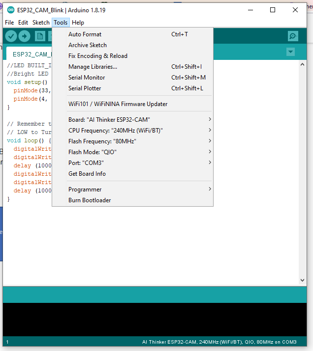
This time I swapped the leads, and have uploaded a blink routine to two of the boards successfully.
I did not have to press the reset button because as soon as the upload began the ESP accepted it.
Then I disconnected USB, removed IO 0 - GND bridge, reconnected USB - and the bright LED started flashing, as per the code.
I havn’t tried the camera code yet but this alone is a great advance for me.
I was actually wondering whether the FTDI was the culprit and was on my way to Jaycar to buy an alternative, no need now.
You’ve made my day.
Kind regards,
Stephen
2 Likes
Glad it worked.
So the problem is the label on the DFROBOT board, wonder if it has caught out anyone else.
Maybe I should put together some information and send to DFROBOT about the labelling.
Cheers
2 Likes
I’ll have a go at camera operation and wifi connection when I get back to my workshop.
Thanks again,
Stephen
1 Like


