
In this project, the focus is the designing of an ESP32 development board that has the capability of WiFi, BLE, UART, 12C, 12S, and SPI. It is a project that will be suitable to run IoT devices. The design of the project is done through the KiCAD EDA and all the production files will be available for anybody who wants to proceed to the production of the board which can be done through the PCBway
Components
- C1, 1 470uF CP1_Small Capacitor_SMD: CP_Elec_3x5.3 Polarized capacitor, small US symbol
- C2, C3, 2 100uF C_Small Capacitor_SMD:CP_Elec_3x5. Unpolarized capacitor, a small symbol
- C4, 1 470uF CP1_Small Capacitor_SMD: CP_Elec_3x5.4 Polarized capacitor, small US symbol
- C5, C10, C11, 3 100nF C_Small Capacitor_SMD:C_0805_2012Metric Unpolarized capacitor, small symbol
- C6, C8, 2 20pF C_Small Capacitor_SMD: C_0805_2012Metric Unpolarized capacitor, small symbol
- C7, 1 10nF C_Small Capacitor_SMD:C_0805_2012Metric Unpolarized capacitor, small symbol
- C9, 1 1uF C_Small Capacitor_SMD: C_0805_2012Metric Unpolarized capacitor, small symbol
- FB1, 1 Ferrite_Bead_Small Ferrite_Bead_Small Ferrite_THT: LairdTech_28C0236-0JW-10 Ferrite bead, small symbol
- J1, J3, 2 Conn_01x12 Conn_01x12 Connector_PinHeader_1.00mm:PinHeader_1x12_P1.00mm_Vertical Generic connector, single row, 01x12, script generated (kicad-library-utils/schlib/autogen/connector/)
- J2, 1 Conn_01x04 Conn_01x04 Connector_PinHeader_1.00mm:PinHeader_1x04_P1.00mm_Horizontal Generic connector, single row, 01x04, script generated (kicad-library-utils/schlib/autogen/connector/)
- SW1, 1 SW_Push SW_Push Fuse: Fuse_0805_2012Metric Push button switch, generic, two pins
- U1, 1 AP1117-33 AP1117-33 Package_TO_SOT_SMD:SOT-223-3_TabPin2 1A Low Dropout regulator, positive, 3.3V fixed output, SOT-223
- U2, 1 STM32F031K6 STM32F031K6 Package_QFP:LQFP-32_5x5mm_P0.5mm
- Y1, 1 Crystal_Small Crystal_Small Crystal: Crystal_SMD_HC49-SD Two-pin crystal, a small symbol
Designing of the Schematic
- Fire up KiCAD and proceed to new then new project and fire up the schematic window and start placing the components as shown below.
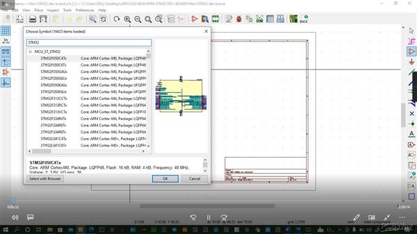
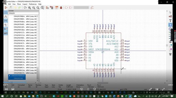
Check for the ESP32-WROOM symbol and place it. If the symbol is not existing you can create your symbol as shown below
Place all other components as you do the wire connections to end up with the schematic shown below: In the schematic, we have done the connection of the ESP32 as per the datasheet available on most component vendors’ sites. We have also done a power supply schematic to power our ESP32 at 3V3.
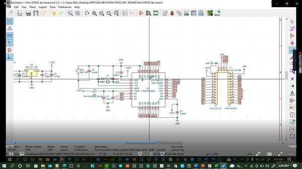
Go to annotation and annotate your schematic to give every component a unique label automatically instead of doing it manually. For example in the schematic above all capacitors have a label of C? but we can give each capacitor a label let us say C1, C2, and so on through annotation.
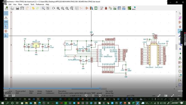
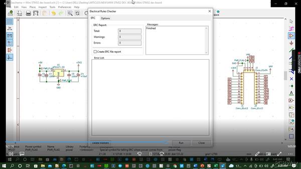
Check the electrical rules to ensure that the circuit is good and has complete functionality. Ensure there are zero earnings and errors before you proceed to the next step
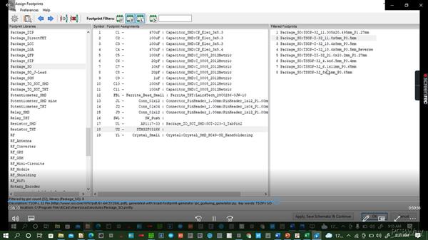
Addition of footprints to your schematics then generate the netlists, save and proceed to PCB layout
PCB Layout
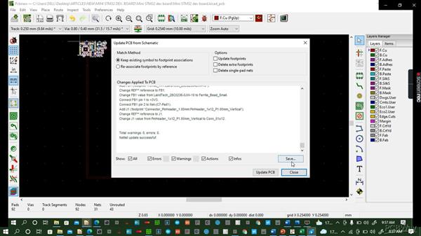
On opening the PCB layout windows, the first step is updating the footprints.
After updating the netlist you start arranging your components in preparation for routing. The components after being placed will give you an outlook shown below:
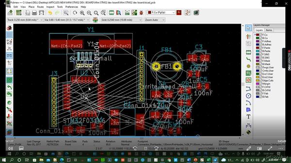
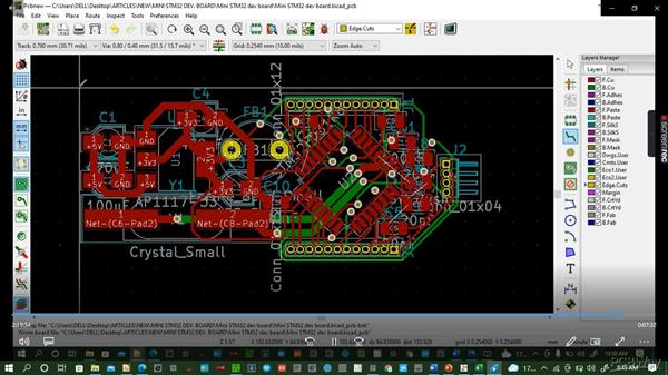
Here, after nicely arranging the components as per the schematic, the routing process starts and at the end of the routing you end up with a product similar to this:
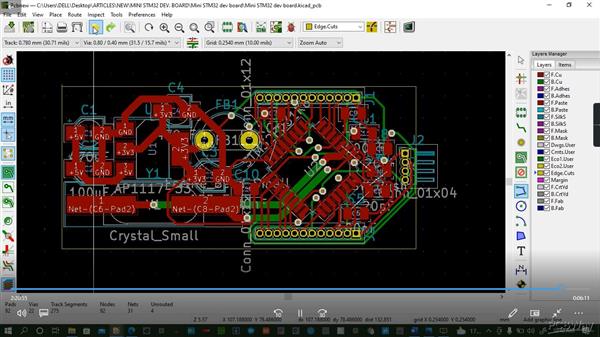
Add the edge cut to give your board a desired shape from your heart.
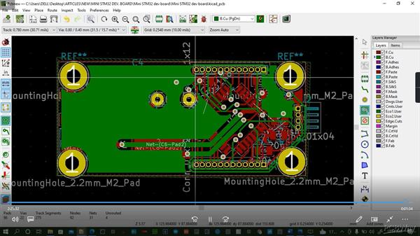
Add copper pores to your board to separate the ground from the active areas.
3D Generation.
Finally, you can convert your routed PCB into a 3D view to have your nice board as shown below.

And this marks the end of our tutorial on how to do the mini ESP32 board design using KiCAD EDA.
The project can be odered for manufacturing through PCBway
How to do it is very easy. You go to PCBway instant quote page and place your order accordingly
