ive got this gps module U-blox NEO-6M GPS Module U-blox NEO-6M GPS Module | Core Electronics Australia that in which i know for certain is hardware compatible with my esp 32 project but im struggling to get a gps lock does anyone have ideas on a fix ?
2 Likes
If you are seeing GPS data being sent to the ESP then the hardware is working and the problem is with the reception of the GPS signal from the satellite. You should describe what you have done to position the antenna with a good view of the sky, and post an example of the data you are getting. Note that if the module has not been used for a lengthy period it can take a long time to get a first acquisition. How long how you waited?
2 Likes
I’ve used double sided tape to secure it to the PCB breakout board for portability reasons
Some times I’m getting a GPS fix others I’m not
As far as first fix is concerned would I be best to leave it on overnight ?
To add the GPS unit is sitting vertical
But where is it sitting in terms of access to open sky? If it works sometimes, then do things change when you place it in a more open position? Can you post some examples of the messages you are getting? If you are getting some correct messages then that indicates that it has the ephemeris data and leaving it longer won’t help - it just needs better access to the satellites. If the messages don’t actually indicate a successful connection then leaving it longer may help.
1 Like
I think you need to mount horizontality. I have 2 running right now, mounted horizontality and no real issue getting a fix, outside of just taking a little time given im running them inside under a tiled roof (so it works as I expect)
i.e. as in the image

2 Likes
i was able to test my set up whilst i was out today and its working perfectly it just took a bit of time to get the initial lock
1 Like
Great to hear Mark!
Been using one for the last few weeks. In the office (which isn’t very GPS-friendly) it takes 10-15 minutes to get a good lock, at home though it takes under a minute. Very dependent on the environment it’s in, and also takes a bit longer on a cold start.
3 Likes
Hello Mark.
I think you need to handle the antenna with care – the less handling, the better.
That tiny connector and cable are easy to damage.
I use this 3D printed frame to hold the antenna to the board:
1 Like
GPS modules need a stronger signal to get a lock than to keep a lock. For the NEO-6M:
Tracking: –161 dBm
Cold starts: –147 dBm
Hot starts: –156 dBm
The 14dB difference between tracking and cold start is quite a lot. If the GPS module can be moved, and it won’t get a lock inside, taking it outside to get a lock then moving it inside can work.
Hooking the GPS module to a USB/serial converter powered by a PC can be instructive. The module can be powered by the USB 5V. Run a program like VisualGPSView (free) to find signal strength. When the GPS module is in a marginal signal, moving it a few centimeters can make a difference. One of mine sits on a window ledge, it took some experimentation to find the exact right spot to get the best signals.
the esp32 board has a means to run add on articles such as this gps module at 3.3 and 5v would running it on 5v as apposed to 3.3v help any ?
I haven’t experience of this exact module. But if it is similar to the modules I’ve used (NEO 6,7; LEA 8 series) they have an on board regulator to provide 3.3V to the chip. The Core doco says it does have a regulator XC6204B2K. So (without definitive evidence) I’d suggest they are powered by something more than 3.3V as there is a voltage drop through the regulator. That said, the signal lines (TX, RX and 1PPS if you use it) are 3.3V level, so don’t send 5V signal to the RX input. The USB/serial modules usually can be set for 5V or 3.3V, the ones I use have a link to set the signal level, either from a 5V pin that is straight from the USB port or a 3.3V pin. So to interface to the PC link the 3.3V pin to the signal level pin, and power the GPS module from the 5V pin.
1 Like
Just for testing, I got a brand new GPS module, soldered the header pins and made up a cable to connect it to a USB-UART module.
The USB-UART can be set to provide 5V or 3.3V via a jumper; so I set it to 3.3 V.
I then connected to USB-UART to the PC and via putty to monitor the gps NMEA packets. It took a little over 2 mins to cold start to GPS fix. Which I would say was fast. The GPS is inside on the table, but near a window.
Keep in mind that the time to fix will depend on where the satellites are in respect to your antenna.
From memory on a cold start the GPS has no idea what satellites should be visible, so it scans looking for one (from its list). This means its scanning alot of frequencies that are not visible, this takes time. When it get data from 1, that can then provide a list of neighboring satellites, so it now has a short list; but not all of those will be visible to you. but some should be, so repeat until you have all the ones in the sky and you now have a good fix.
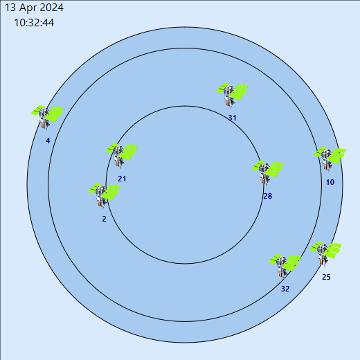
for reference this was my test setup

In the 2nd image you can see that the it has 8 sats, but south (down) could be a bit of a dead spot if I have things blocking from the east/west.
2 Likes