This is a placeholder topic for “Gravity: Liquid Flow Sensor (G1/4)” comments.
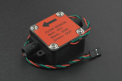
This Gravity: electromagnetic-based liquid flow sensor can measure the flow of various liquids like water, diesel, engine oil, milk, paint, detergent and…
Read moreThis is a placeholder topic for “Gravity: Liquid Flow Sensor (G1/4)” comments.
This Gravity: electromagnetic-based liquid flow sensor can measure the flow of various liquids like water, diesel, engine oil, milk, paint, detergent and…
Read moreHi, how do I connect this sensor to the 13 mm hose? Do you sell the connectors? Thanks
Hey Harjinder,
Welcome to the forums!
We don’t have the threaded connector for that product regretfully, though my recommendation would be to use a bit of heat and a cable tie to secure the tubing onto that threaded part, which should be more than sufficient to hold that tubing on.
Cheers,
Blayden
Hi All.
I have a quick (or maybe not so quick) query
In the specification list it says
" Output: NPN Pulse signal"
This suggest to me that the output is “open collector / drain” which has been the case with any sensor I have dealt with.
BUT further down we have
" Output Pulse High Level: >DC4.7V(Input voltage DC5V)"
" Output Pulse Low Level: <DC0.5V(Input voltage DC5V)"
Which would suggest the output is driven HIGH or LOW by a Schmidt trigger (most likely) or OP amp. The wiring diagram connecting to Arduino with no pull up or down resistors supports this theory.
Could you please clarify. The DFRobot Wiki page does not offer any clues except for the suggested wiring diagram.
By the way the line " * Output Pulse Low Level: <DC0.5V(Input voltage DC5V)" on your page is incomplete. It stops after “Level:”
Cheers Bob
Hi Bob,
I’ve just hooked one of these sensors up to my bench power supply and measured the default state of the output pin. The signal pin measures very close to 0V on the output when powered up with no flow.
It seems what DFRobot were trying to convey is that the digital input will normally read <0.5V, then briefly read >4.7V before dropping back below 0.5V. By counting the pulses a user can then infer the flow rate as it outputs 540 pulses for every Litre of fluid that passes through it.
Since the wiring diagram does not include any form of external pullup/down resistors we can assume they aren’t needed to measure an output from the device, or they are included internally.
Looking at the sample code they’ve provided on their product wiki the device is counting a pulse for each rising edge detected though admittedly you could still measure a falling edge for the same outcome independent of what the idle state of the device was as it’s only the pulses you need to detect. Ultimately for the end user the code they have provided will work for an active low, or active high device.
As for the incomplete line on our product page, I’ll have that fixed up shortly.
And you can get our latest projects and tips straight away by following us on:
![]()
![]()
![]()
![]()