In most Arduino projects, relays are the first choice to drive some large current device. It requires a certain amount of current to drive the internal coil to pick-up…
Will this MOSFET trigger at the ESP8266 PWM voltage levels? I’ve just transitioned from Arduino to ESP and all my existing MOS modules needed 5V to trigger.
Yeah this module should work fine, the RPi has the same 3.3V logic level so look for that in terms of logic levels.
And it looks like there is a gate driving circuit onboard (haven’t had a look at the schematic so might be something else)
Just looked at the circuit. Yes that item marked is an opto coupler to drive the gate.
This is a P channel “High Side” switch, not an N channel “low side” switch which is more “normal” when used as a motor or relay driver.
Although the “Vin” and “Vout” instead of Drain and Ground provide a clue to this It might be a good idea to mention it in the description I think.
Cheers Bob
Bob - the product description is pretty light on for details. Just to confirm though, P MOSFET are when you switch the live line and N is when you switch the ground? I haven’t had to think about these things since the late 90’s and I wasn’t very good at it then either.
Hi Dean
Basically yes. “High side” switch is switching the live line to the load and “Low side” switch switches the ground or low side of the load to ground.
Cheers Bob
I’ve just started playing with this module but I’m not having the best of times with PWM. I’m using Adafruit’s TLC5947 24-Channel 12-bit PWM LED Driver - which I’ve successfully used with other mosfets with quite smooth dimming, but now I need something more higher power - and the resolution is very low, quite obvious stepping with dimming and my LED seems to reach nearly 100% brightness at around 40%.
I noticed on the product page the switching frequency is 1kHz which matches the PWM frequency of the TLC5947, however it also says the “switching character” is T(on)=20us/T(off)=50us. I’m wondering if that slower turning off time is making the dimming steps appear quite big.
Hi Andrew
Welcome.
A circuit or schematic would be useful to get more realistic response.
This device is a “high side” switch using p-ch Mosfet. That means you switch the voltage side as against the more usual ground side “low side” switch.
I have not looked at that TLC5947 device in any detail but I strongly suspect it would drive the gate of n-ch Mosfets directly as low side switches. That is switching the ground.
The subject of this thread actually uses the logic signal to operate an Opto Coupler which switches the p-ch Mosfet as a high side switch.
Without sighting a diagram of some sort I would suggest you are trying to use the wrong combination of bits for your purpose. You can get some pretty big and robust n-ch devices. How much power do you need? This device is good for 20A and a heatsink is recommended above 10A and there are plenty of n-ch devices that can handle far more than that although for large currents heat sinking is still required.
Cheers Bob
Here’s a diagram of what I’m doing. My assumption was that using a P-channel mosfet wasn’t much different to using an N-channel mosfet if the logic is going via an opto-coupler - perhaps I’m wrong?
The PCA9685 has some settings to adjust the PWM frequency and phase (in the case of using servos instead of LEDs) but my testing so far yields slightly different curves but still in a highly steppy manner.
You certainly are!!! I don’t quite believe I read that properly.
Do you know the difference between an NPN and PNP transistor???
The n channel and p channel Mosfets are the same. the operating conditions are reversed for a start. I think that is enough difference to be significant.
For high side switching P channel devices would be used where the voltage supply is switched to the load.
For low side switching the positive supply is connected to the load and the “earthy” or ground side is switched to ground with an n channel Mosfet..
You will have to find a higher voltage rated device. Allow a bit of fudge factor. Go for 50 or 60V. Resistive loads do not require any flyback diodes but if using an inductive load a diode is mandatory or the Mosfet will quickly fail.
Any PWM system will be “steppy”. This depends on the number of steps it takes to go from 0 to 100%. A common number of steps is 255 but could really be anything depending on the design of the PWM generator. By the way the “frequency” of the PWM signal has nothing to do with this.
I think the device you kinked above
is a low side switch with n channel Mosfets. But as is the norm these days detailed information such as a schematic is pretty well non existent.
The one in your diagram above is (I think, the detail is impossible to read) a high side switch which would use p channel Mosfet.
Cheers Bob
Heh, yeah I don’t think you did and I don’t think I worded that well. I understand the difference between NPN and PNP transistors, but what I wasn’t sure about was that when triggering the gate is done through an opto-coupler on a module like the DFR0457, there doesn’t appear to be (and there isn’t any documented) a difference required on the logic side - the polarity of the actual switching seems irrelevant to the logic. I’m wondering how the logic would need to behave differently if I’m not understanding that part correctly. Of course if I’m switching on and it turns off then the logic needs to be inverted, but that’s not the case here.
The steps on the lower end of intensity are HUGE. And my previously used (but now failed) mosfets demonstrated the steps can appear much finer.
Going back to my original post, I noted in the specs for the DFR0457 module (not just the mosfet itself) that the switching off time is longer than the switching on time - over twice as long. I’d imagine when using a PWM signal that a non-balanced timing between on and off could wreak havoc with the intended output.
If the time to turn off is too slow for the frequency being pushed then the outcome may be that at certain intensities the gate would remain closed across multiple low cycles, leaving it closed for longer than intended with the appearance of the light being brighter than intended. This seems to be my observation.
I found this user here DFR0457 Slow Switch Off Speed- DFRobot Forum doing a deep dive into the timing of this module and finding some problems. It all leads me to think perhaps this module isn’t entirely suitable for PWM applications.
Thanks, I’ll look for something around that voltage. I honestly have no idea how I overlooked the 30v limit on my previous ones, I think I saw the current rating and clicked “buy”!
Hi Andrew
Where did the 20µec and 50µsec come from. If this is true this would certainly have an affect on the lower duty (motor slower/lamp dimmer) cycle settings.
Just what sort of device is fitted. All the schematic (yes I found one) says is Q1. Big help.
I just had a look at some N channel Mosfets and the rise and fall time is only a few nSec which is a factor of 3 zeros and at normal PWM frequencies can be ignored.
I suppose P channel Mosfets could be worse in this regard but I don’t think that much. You have an Opto Coupler and transistor here which might add a bit and the overall speed might be in µsec but I doubt it.
If you can see any markings on the fitted Mosfet let us know and we can have a look.
Cheers Bob
The package on my module says HW70P04K. Searching for on and off times for that reveals 10ns and 40ns respectively. So the additional circuitry is adding orders of magnitude of latency.
That could be correct. Maybe those numbers are a measurement of the module overall performance which would not make it very suitable for PWM type use. Maybe just ON/OFF.
To comment I would have to measure for myself which I am probably not going to do.
Later today I will do a bit of research on that driver board you are using. I am not sure driving an opto coupler is the correct use. I strongly suspect it is meant to be a direct Mosfet Gate driver. Required if high speed switching (mainly to reduce heat build up) is required.
A Mosfet Gate has some capacitance which is mostly significant value. When switched ON this cap has to be charged and will momentarily appear as a short circuit. This requires current which a usual micro cannot provide so a current limiting resistor is placed in series to keep this to a safe value. This has the effect of slowing down the switching. If fast switching is required this Gate cap has to be driven and the current supplied from elsewhere. Then the Gate resistor is usually reduced to about 10Ω. This is where the driver board you are using comes in. To supply this current. I think. I will check later.
If I am correct you would get better results with a simple N channel Mosfet as a low side switch which will handle your PWM easily.
Cheers Bob
PS: My search for HW70P04K did not produce any results.
Typo maybe??
Hi Andrew
Just having a look at that driver board.
It seems to be a dedicated LED driver but there is no reason you can’t drive anything that requires PWM. Bearing in mind that servos will require a PWM FREQUENCY of 50Hz (or a PERIOD of 20mSec).
I came across this in the chip data sheet
All showing low side switching with N channel Mosfets. But there is no reason not to have a mixture if required.
I did not look too closely at the minute details. All the PWM outputs might have to be the same FREQUENCY, maybe not but you will have to dig in and investigate.
My suggestion for your lamp dimmer would be to ditch that switch module and wire an N ch Mosfet as a low side switch. Replace the LED in the above drawings with your lamp. Although the drawings display LEDs in groups they can all be individually controlled as depicted by the 12V bit. Core might have a module with the bare N Ch Mosfet fitted but if not Freetronics used to have one. A module might be easier for you but there is no external extra components really so it should not be too hard to handle just the bare device. I don’t think a pull down resistor is required as I think all this is handled with the driver board.
That chip gives you lots of control which is covered in depth with the data sheet but probably is handled by some sort of a library. I have not got time (or the knowhow, being basically an analog person) to go into all of this at the moment do will leave further digging to you.
This should clear up some questions.
Looking at the Mosfet figures I note the input capacitance is a pretty massive at 6.46nF and the module discharge resistor is pretty large (13k I think, I haven’t got the schematic open at the moment) and I would think this would extend the off tome a fair bit.
Cheers Bob
PS:
As a point of interest the combination of 6460pF and 13kΩ has a time constant of about 84µSec. That is where the cap has lost about 67% of the voltage across it. Might account for some of that measured OFF timing.
I think my math is right.
Hi Andrew
Don’t forget inductive loads (relays, motors etc) will require a flywheel diode (Schottky) across the load. Cathode toward positive supply.
Cheers Bob
Hi Andrew
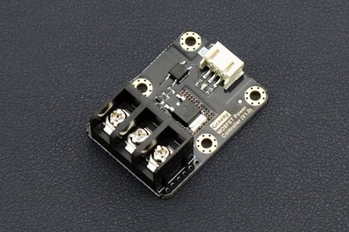
Just re visited the schematic of that switch Gravity: MOSFET Power Controller SKU DFR0547.
The discharge resistor is 33k NOT 13k as I thought.
This makes things worse. A time constant that is now 213µSec. NOT 84µSec as I first said.
Makes things worse.
Cheers Bob
That timing is pretty critical for PWM. I’ll keep these modules for building my son some backyard traffic lights but I’ll give them a miss for dimming my lounge room lights. Core might want to note on the product page that this module doesn’t excel in PWM applications.
Hi Andrew
That actual timing effect would depend on exactly at what Gate voltage the Mosfet switches. You will note on the Data sheets the threshold gate voltage has quite a range so the EXACT timing would depend somewhat on the individual device.
The important bit would be the DIFFERENCE in ON and OFF delays. If they are both the same then it would not matter as long as the RISE and FALL times are quick enough. Rise and Fall times are different to on and off DELAY. In this case the R/C delay has a different R component value of charge = 3.3kΩ and discharge = 33kΩ. Not exactly ideal if you are using a higher frequency PWM as this becomes a larger percentage of the duty cycle at smaller values (slower/dimmer).
That is why Mosfet drivers are used when fast switching is required. This could be in the form of NPN/PNP transistor pair or dedicated Mosfet Gate driver ICs which provide a low impedance source/sink drive (for a short time) allowing this series resistor to be as low as 10Ωwhich usually gets the time constants down to nS or pS. This also prevents heat build up at higher currents due to slow switching.
As with most things electronic there are quite a lot of things to consider.
Cheers Bob