Hi! I’m planning on powering a project consists of:
I’m not sure what battery to use, or how many batteries to get. For now I want the form factor to be very small, and I’m not planning for it be used for long (like 5hrs), so I’m planning to just get 1 battery. This particular ESP32 has a lithium battery charging and level detection feature on-board if the battery is connected to the BAT pin, so I was thinking of getting this 3.7V Lithium Ion 2400mAh Battery, then use a 5V step up regulator to power the sensor and NFC chip, and a 6V step up regulator to power the motors and servo.
This is the diagram of what I’m planning on doing. The ESP32 itself shouldn’t be powering anything, only controlling. When it’s sleeping, everything else should be turned off or is also sleeping (except the ultrasonic sensor to wake this up).
Will this be enough to power the project? Am I using anything incorrectly as well? I’ve never used a switching regulator before, and reading that “this can get very hot when vin is much lower than vout” slightly concerns me…
Thank you
1 Like
I will leave it to others to talk about the best options.
From my math, assuming no lose in conversions (which there will be), and assuming the battery can deliver 100% of its power (which you will also have some losses) I get about 3.5 Hrs of run time base on the power needs.
The end result would be lower, but it does raise the question…
How much run time do you want ?
1 Like
Hi Kheng
Welcome
Let’s take this apart.
Firstly the all important power requirement.
Th evaluate this we have to convert everything to Watts. There is no getting around that.
Using your numbers above we have 18mA (I assume each) = 36mA plus the servo @ 130mA = 166mA @ 6V = 0.78W or 780mW.
Then @ 5V we have 155mA = 0.775W or 775mW
Total 1.556W or 1556mW.
This @ 3.7V (nominal battery voltage) = 421mA or 0.421A
We must add to this the conversion factor. There will always be some loss. This could be anywhere between 85% to 95%.
So worst case 85% this would be 1.831W = 0.495A or 495mA.
Add the ESP32 200mA = total 695mA from the battery.
As Michael says about 3hr run time with a single cell. You could probably expect about double with 2 cells in parallel.. I personally would go about 50% higher to allow some head room or fudge factor for unforeseen additions. Say 3 cells in parallel.
Just about says it all.
Now the rest.
You need about 1k in series with Mosfet gates. The Gate is a short to ground at switch on so the 1k is a current limiting resistor.I have been into the reason this is so several times so am not gong to repeat.
I am not convinced the 2N7000 is the best choice. I think switching will be pretty marginal at 3.3V if it switches at all. The data sheet gives figures for 4.5V and 10V and the graphs don’t look very promising. This Mosfet does not switch a great deal of current and I assume the 18mA quoted above is running current. Wha a lot of people forget is the inrush current which will be the same as the stall current. You need to add this to the power requirement too as this has to be provided at start up. These days i think there are Mosfets around which will switch fully on at 3.3V. The series Gate resistor is always required.
The 1N4004 are certainly not the best option for flyback diodes. Too slow. The MBR20100CT looks like a bit of an overkill but is a tried and proven device used extensively in this application. Actually 2 diodes in parallel in the same package. Connect them in parallel. As both motors are in parallel only 1 device is required.
That’s about all for now. Might think of something else later.
Cheers Bob
2 Likes
Thank you so much for your replies Michael and Robert! I’ve gone and implemented Robert’s maths into a spreadsheet Deck box power consumption calculation - Google Sheets. I would appreciate your opinions on this in case there might be any mistakes. One thing I didn’t mention to you guys was how long these components will stay active/idle for. It’s true that if all of them stay up and running 100% of the time, I would only get around 3hrs out of it. However from my data gathering, this thing would sit in idle at least 95% of the time, and even when active, only some will be while others will be off/sleeping, so 3hrs of active time is actually plenty good 
Re: mosfets, I don’t mean to expand the scope of this post, but since you mentioned I’d also appreciate the help here as well (also first time using mosfets, so pardon the inexperience). I mostly chose 2N7000 because I got recommended at the store. The Vgs(th) is 3V max, which is the same with the voltage of the output pin, so worst case scenario the fet will still turn on. The output graph also looked fine to me . . . “3V Vgs, my Vds is 6V, that means I’ll get ~0.2A through the motors, which is way more than 36mA required to run them”. That’s fine right, or was I missing something else?
I also didn’t know mosfets need to be considered as part of the power requirement too. How would you include them in the calculation?
Re: diodes. I assume “too slow” means I need a shottky diode with a lower voltage requirement for conducting than just a normal diode? Would the 1N5822 be more suitable and less overkill?
1 Like
Hi Khang
I can’t see where I said that.
You don’t. The current through the Mosfets is the same current through the motors/servo. Only has to be considered once.
The whole scenario above is worst case. That is with everything active at the same time. You have to consider that this is going to happen at some times. I have found over the years that if you DON’T think of this you will get into trouble when it does happen. And it lessens the chance of unexplained funnies upsetting thing in a random fashion downstream. In other words allow for everything.
So please do your own math. On my estimation the max out of the battery at any one time would be about 700mA which a single cell I think will handle OK. If you estimate 5% duty cycle is correct your run time would be far in excess of the worst case 3hr.
The speed of a diode I supposed could be expressed as the time it takes to look like a diode. The 1N4004 series is a power diode built for up to 100Hz. The flyback pulse could be much faster which means part of the pulse will be missed while the diode catches up. A schottky here is preferred more for the speed than lower forward voltage drop. You get away with these across a relay because of the relative slow operating time of these devices. PWM drive is a different ball game.
Getting to the 2N7000
I am only suggesting you use a more suitable device that will switch fully ON at 3.3V. This device will only be partially ON at that Gate voltage.
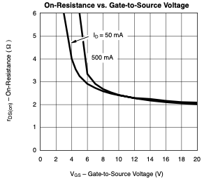
I don’t know where your graph came from but the corresponding one on the Vishay data sheet tells a different story
and the ON resistance @ 50mA and Gate V 3.3V looks like about 6Ω which is quite high for a Mosfet which should be in the mΩ region.
Another one which shows at 3V it is still down in the sharper bend in the curve which suggests it is not fully ON.
In summary I personally would not use this for this application. But I stress that is only MY opinion.
Cheers Bob
2 Likes
You need to add this to the power requirement too as this has to be provided at start up
Sorry I think I might’ve misread this. I think you just meant “make sure to pick the mosfet that your esp can actually start”, but at the time I thought you meant I needed to include this in my power consumption calculations.
In other words allow for everything.
I love this advice, thank you very much! I’ve updated the spreadsheet to include “everything on” scenario, and I got about 3.9hrs. It’s about the same as what you guys came to, which gave me confidence that my calculations for the expected time with some components on and some off are also relatively correct, so sounds like this battery is good for purchase!
A schottky here is preferred more for the speed than lower forward voltage drop
Understood, thank you.
Re: New mosfet, thankfully I haven’t purchased those, so I’m free to look for new ones! I’ve found this one TN0702 which seems to be much better for this application.
There wasn’t an Rds(on) vs Vgs graph, but they did have this table which specifies that Rds(on) will be 2.5Ω (not in the mΩ unfortunately?), and 200mA

And this graph showing 3V just above the sharp bend
Would you prefer this over the 2N7000?
Thanks,
Khang
Hi Khang
Yes I would. The operating voltage is low (max 20V) but that should be OK.
The data sheet gives some numbers at low Gate voltages which suggests it will be switched ON at something like 3V so this is better for a start.
This graph is nearly like the one in the Vishay sheet and clearly shows less than 2Ω at Gate voltage of 3V which is way better than 6Ω+.
Don’t forger the 1kΩ in series with the Gate drive to protect the GPIO. Definitely a must with this Mosfet as the Gate capacitor is fairly large at 130 - 200pF.
Cheers Bob
1 Like
Thanks Bob, this is what you meant right?
1 Like
Hi Khang
R2 and R4 yes that is what I mean.
You have not shown the ESP32 power connections. Make sure the ESP32 ground is connected to the common ground point.
The servo ground should be connected to ESP32 ground for a return path for the PWM signal. As you have it this happens via the Mosfet. The may be OK, I don’t know only trial will tell. As it stands the drain (servo ground) will sit slightly above “Ground” so you will just have to try it.
Cheers Bob
1 Like
Hi Bob
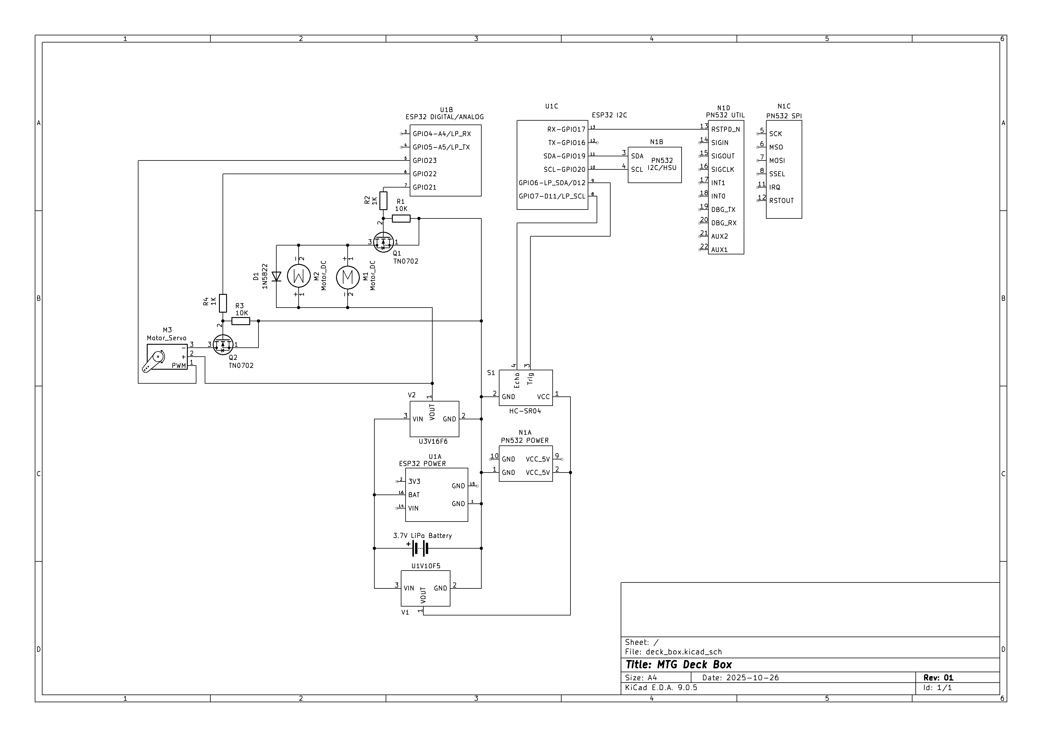
I’ve splitted the pinouts of the ESP32 into smaller parts so it’s easier to connect things, but it might’ve been harder to read because of it . . . I have updated the schematics since though, so here’s what it’s looking like now (I’ve changed to use 18650 thanks to your answer in one of my recent posts and help from a friend  )
)
You’ll find the power connections for the ESP32 at C2 for part X1A
Thanks
Khang
1 Like
Hi Khang
Well you certainly have made some changes. Half of it won’t work I don’t think.
R7 should really be from Gate to ground. ie; on the other side of R6. Where it used to be. Was R1. Same applies to R5 (was R3) on N2. Why did all the component numbers change. Only confuses the issue when trying to refer to bits in texts such as this. There was no need to do tis.
P3 used to be N channel Mosfet. Why is in now P channel? As it stands the motors will run flat out continuously due to the Mosfet body diode. Don’t forget this little beast.
What are N1 and P1. Looks like some sort of push ON push OFF arrangement.
Due to the same body diode in P1 it will appear to be ON continuously.
Haven’t bothered to look closely any further. The rest seems to be pretty well unchanged.
Cheers Bob
It would make life simpler if you delete this schematic and re annotate to agree with the earlier schematic document then replace it.
1 Like
Hi Bob
Well you certainly have made some changes. Half of it won’t work I don’t think
Thanks! I was in the middle of updating the schematic when I saw your replies, so you might be right that half of these won’t work. I just wanted to address your concern re: power for the esp, but I really appreciate you asking about other parts of my schematic as well because your insights have been very helpful for a beginner like me, so I’d like your help for these parts too.
Why did all the component numbers change
Apologies for the confusion, I got advice from other peeps saying I should number my parts from power going outwards - they prefer starting their evaluation from the power source. But it seems it’s creating more confusion than it’s helping with readability…
R7 should really be from Gate to ground. ie; on the other side of R6. Where it used to be
The reason for the gate resistor change was because of this video https://youtu.be/AwRJsze_9m4?si=bFP26NUwiLv3uh9-&t=277 (from 4:43 to 5:43). Apparently I was creating a voltage divider with the previous setup, so less voltage would be provided to the gate, but we just want to limit the current passing through right? Or were you intending on creating a voltage divider? Or was there a mistake in the way I interpreted you or the video?
P3 used to be N channel Mosfet
Yes it was, and I did change it to pmos, but I also added a push button to activate them. There are 3 reasons for this update:
- I want the user to be able to control the motors - hence the button
- There are times I don’t want the user to be able to turn them on, regardless of input - hence the mosfet so the esp can lock/unlock it
- I want the user to be able to control the motors while the esp is sleeping too. The esp disables the pin output whenever it sleeps. Using nmos won’t work because the pin to the gate needs to be kept high to keep the motors running, and I’ll lose this if I put the esp to sleep
What are N1 and P1. Looks like some sort of push ON push OFF arrangement.
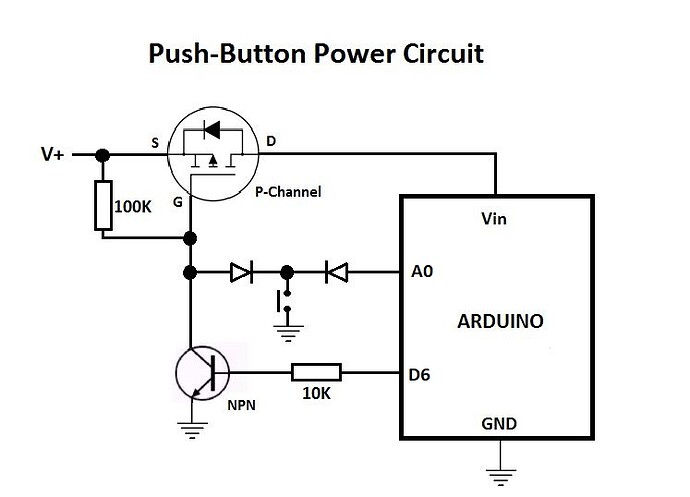
Yes that is correct, that came from this video https://youtu.be/a63o-HJEmI0?si=MI-t9T2pPDZGu0ud&t=100 (explanation starts 1:40). I tried to recreate that in the schematic so hopefully I got that right. I want the user to turn on the project by pressing a button, then the project can turn itself off if it detects a voltage below 3.1V from the battery (googling says 3.0V is the minimum LiPo can provide before going over-discharge)
I need the same button to be able to power off after long hold as well, and I think I can do something similar to this Switch Microcontroller on and off with a button and mofset - 3rd Party Boards - Arduino Forum (have not updated the schematics for this yet)
I’m not sure about the BJT though. Both the nmos and npn seems to only be used as switches, so I assume it’ll work fine if I use the nmos combining the post and the video. The parts are not all here yet so TBD
Cheers
Khang
1 Like
Hi Khang
Re Gate resistors (10k) to ground. What that video says is true but it has been convention to connect to ground to get as fast a discharge as possible. The voltage reduction due to voltage divider effect is minimal (4.54V) and I think if the Mosfet is sailing that close to the wind it maybe should be replaced by a lower threshold voltage type. As most of your application is slow it probably won’t matter so leave it.
Did you not heed what I said about the body diode. As it stands the motors will run full speed while the button is pressed. Irrespective what the Arduino does. You may as well not have the Mosfet and Arduino connection. They do nothing. The body diode will conduct at all times. For a low side switch you need an N channel Mosfet.
Power switching. I think I can see what you are trying to do here. In your schematic P1 Source and Drain are reversed. The way you have it P1 body diode (there is that little beast again) will be biased ON and be conducting at all times, Won’t switch off. Reversing the Drain and Source will fix this.
Refer that last little schematic. The Mosfet will turn on and remain so while the button is pressed. To stay ON the Arduino must start up and D6 goes HIGH. The transistor will keep the Mosfet ON until D6 goes LOW.
What does the diode connected to A0 do. While the button is pressed A0 will remain LOW, after that nothing will happen and A0 will float. What is the purpose of this?
You might have to give this bit some serious thought.
This too. You won’t be able to do this if the Arduino is asleep.
You are right about the confusion. I would be a little wary about some of the advice on the internet, especially YouTube. Some is quite good but there is an awful lot of absolute garbage. As for the numbering convention. I have been dealing with schematics for some 65 years and have never come across that. True some manufacturers may have laid down protocols but most changes are made before publication. Once released and published any changes must be by way of “change orders” so there is always a paper trail.
Of course in this scenario that just cannot happen. Schematics will be published and changes made, that is just the nature of a forum such as this.
But confusion CAN be minimised if once you have produced and annotated a schematic you DON"T change the annotation of existing bits. Add to the inventory if needed. Delete if required but make a note of the deletion (and additions) and DON"T re issue that component number. At the end of the day when all is checked and locked down you can hit the “Re Annotate” button (most decent schematic editors have this facility) and re issue the document in ts final form to clean it up if required.
Cheers Bob
As an add on. Mosfets have one property that some may not be aware of. Once the Gate capacitor is charged and the Mosfet is ON removal of the Gate voltage will do nothing. UNLESS the gate capacitor is discharged the device will remain ON for sometimes a very long time. In fact this could be weeks or more. The device input will be up in the TΩ region and will take a very long time to discharge the cap without outside assistance.
You can even remove power and come back some time later and the device will still be ON when power restored.
1 Like
One thing to keep in mind with those multiple step-up regulators is the ‘startup surge.’ When those DC motors or the servo kick in, they can cause a momentary voltage sag on the battery line that might brown out the ESP32. Adding a nice chunky capacitor (maybe 470uF or 1000uF) across the battery rail can really help smooth out those spikes and keep the logic side stable!
1 Like
Hi Brittany, Khang
Another reason to always use a separate power supply for motors and servos. Removes all those problems. Aaahh but when are people going to listen.
Cheers
1 Like