I’m a software guy, but interested in IoT devices. I know almost nothing about the physical aspects of electronics. I have purchased a Sonoff ESP2866-based switch that I’d like to flash with different software, and I’ve looked at the following video on how to do it
I’ve managed to solder the pins to the board, but I don’t know what interface to buy to connect the pins to the USB interface on my computer (a Macintosh, by the way). Any guidance will be greatly received. S t u a r t .
Hey Stuart,
Thanks for getting in touch. It sounds like you need an FTDI device capable of connecting your ESP to your Mac and reprogramming it. I’ve never used the Sonoff devices though, so that process might need to be investiagted further. Check this cable out though -
Okay, it’s been a while since I started this journey, but I’m back to looking at programming the ESP device again. In the meantime I’ve spoken to a friend who has done some programming of an ESP device using his Mac with some success. My situation is a little different however.
In my friend’s case, his ESP board has a built-in USB port allowing for direct connection to his Mac. In my case the Sonoff board simply exposes the pins for a serial connection to the board. I’ve managed to solder a series of connectors to the Sonoff which will give me access to its programming interface.
I purchased the FTDI cable mentioned earlier in this thread. And this is where I’m now stuck.
I have the following software installed:
macOS 10.13.5
Arduino 1.8.5 (with the Generic ESP2866 module installed)
Hey Stuart,
I’ve not had any experience with connecting a device to a Mac OS and from what I recall, it’s a little different to normal. Perhaps there’s someone from the community that might’ve dealt with the process on a Mac?
Hi Aidan
Finally getting around to using the CE09543’s I bought ages ago… going thru your article on using these with Arduino the link to adding the boards doesn’t work so not sure where to go from here…
Please advise
Thanks
Darryl
Even if you found that procedure it would likely be out of date.
The first step is to add the URL for your boards manager. You do that by selecting File\Preferences from the menu in the IDE then selecting the edit symbol for ‘Additional Boards Manager URLs:’ at the bottom.
After it is added you should be able to search for ESP8266 in the boards manager pane, and select ‘esp8266 by ESP8266 Community’ and install it. The correct board for the ESP01 is Generic 8266 Module.
In the meantime I figured that part out… the latest IDE is somewhat different to even the Adafruit article (which like always is very good)…
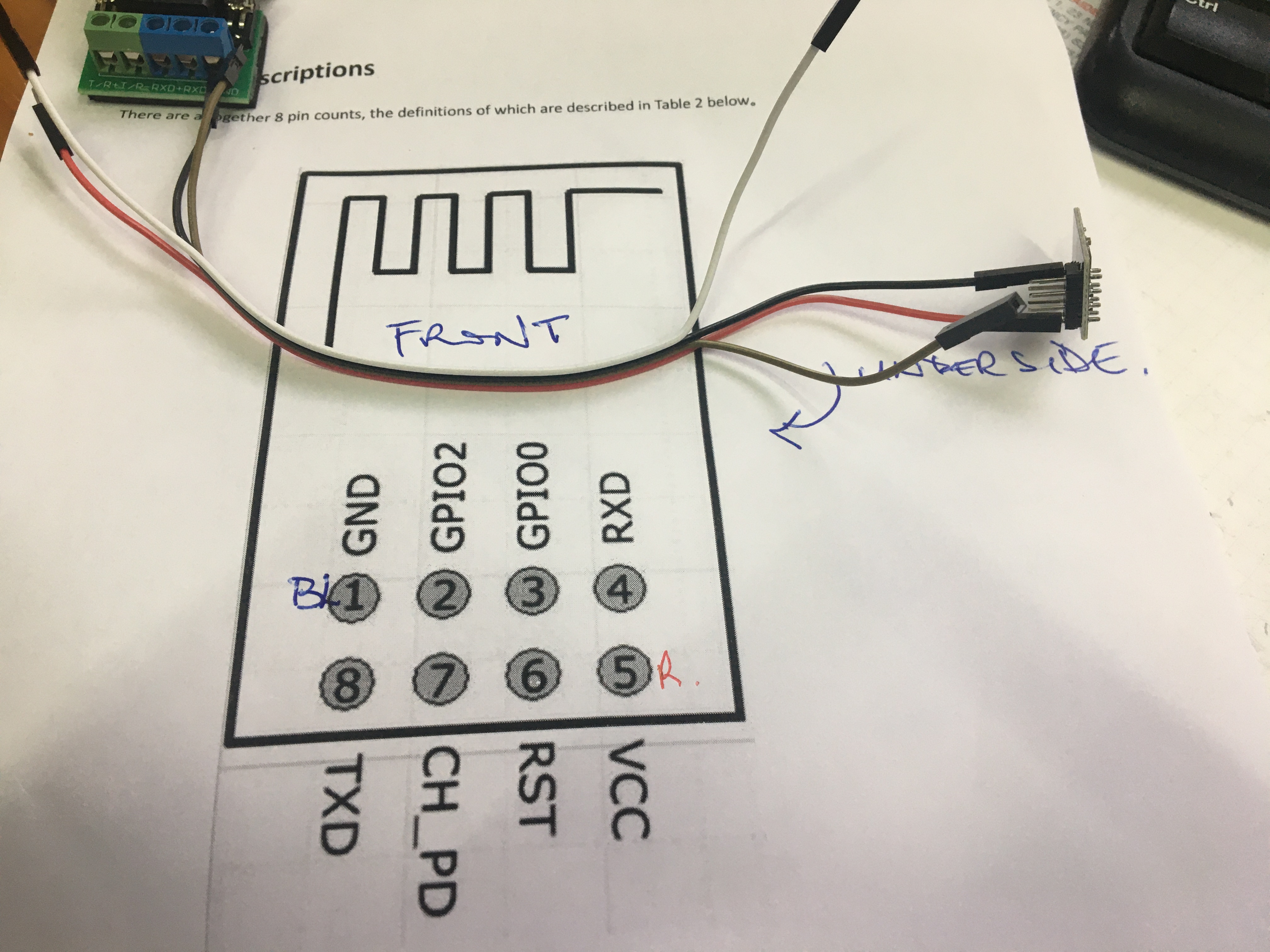
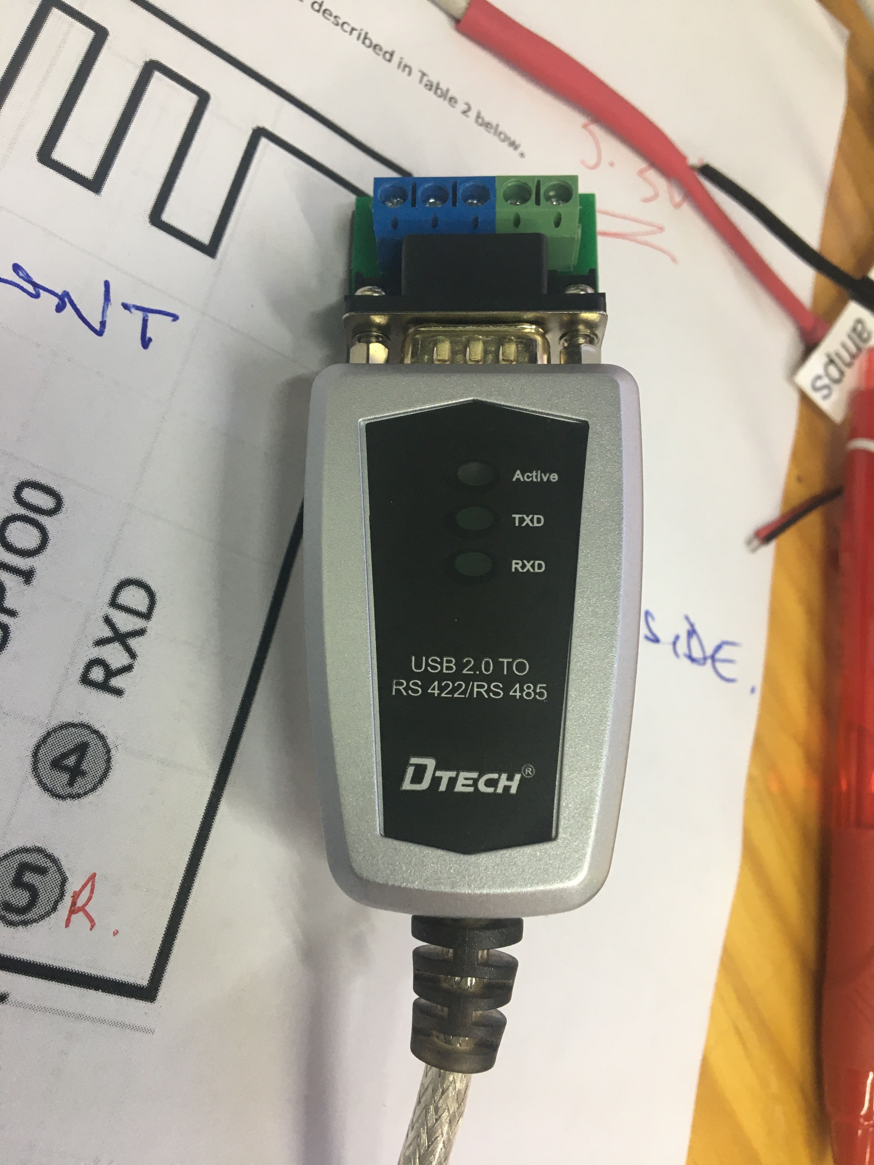
It’s now have a comms issue I have asked Aidan but you might know, connecting the ESP8266 with my serial FIT0272 which has the DB9 to terminal adaptor… the designations on the adaptor are not according to DB9 identifiers and I’m waiting for clarification before I hook up so I don’t smoke the board, see attached
Is the FIT0272 RS232 or RS422/485 ?
The esp9266 TX/RX should be TTL level and would need a TTL to RS232 adaptor.
There are lots of different types just need to make sure it works on your OS of choice, but something like
USB to TTL Converter - CP2102
This will take the TTL/UART RX/TX and convert that to a USB-RS232 on the computer side, then you can use COMx as needed.
I don’t think a FIT0272 will work. The identifiers on the connector will be different than you would usaully see for a DB9 connector because they are for a balanced-pair protocol and not a UART.
Some of this can be preference while some will be critical.
In short, what ever the adaptor make/model is, it MUST support the UART/TTL to connect to most chips directly. There are many serial protocols each with different electrical/voltage levels. e.g. UART on an ESP is normally 0-3.3V
So on one side it will need to be UART level. The other side of the adapter would be whats needed for the connection to the next device.
e.g. It could be RS232/RS422/RS485 and so on… for programming and connecting to a PC using a USB-UART is normally the most convenient.
From here it starts to depend on what is more important to you.
A perfect adaptor such as the one @Jeff105671 recommended, as it connects to all the important pins on the ESP8266 (i.e. TPH-106167) While I have not used that board Im betting that it would provided the simplest/best user experience for programming the 8266 chips. and at a guess it will also provide the power (from the USB) so it would just be connect and program.
Looking at the one I listed, It could be 5V only, in which case NOT that one.
As a more generic USB-UART adaptor it often means you need to work out other things (e.g. put into firmware flash mode). The reason that sort of thing would be my go to is they are normally more flexable for other things, not just connect for programming.
So for simplicity I would go with the one @Jeff105671 recommended to make you life easier.
Keep in mind you can always make/get some hook up wires to let you use it the way you want.
Where would I be likely to find a guide to the operation of the TPH-106167? There is nothing (apparent) at CORE and The Pi Hut doesn’t even recognise the part number!
It’s a generic item, so there might not be a specific guide.
In fact, no guide should be needed. Plug it in to the USB cable and it should appear as a COM port, plug the ESP01 into the header, select the COM port in the IDE, select generic 8266 as the board, and hit the upload button. You might have to press Reset when the upload finishes, but I think the latest version of the IDE now does that for you.
If you do a www search you will find a number of articles on using a USB adapter with the ESP01. But note that they are usually very old, and often refer to modules that need to be modified before they work properly. AFAICT the TPH-106167 has all the features you need and works just fine as is.
There are only two possible things to consider.
The first is that the header itself is not keyed - be very careful to plug the ESP01 in the right way around. Most of these adapters have a clear indication as to which way the ESP01 should be facing. If not, identify GND or 3V and that will confirm the direction.
The other is that that you might need to install a driver. There are only a couple of different drivers ever used for these adapters, and the drivers are very readily available and are likely already installed. If not, the install should be automatic. I can’t tell what driver this particular unit uses but if there is a problem you can post back and someone will find the right driver.
The ESP01 is old, but it is still a very capable device and the small footprint is a big advantage. For instance, I use a pair with a simple ESP_NOW sketch to provide a wireless serial connection between the PC serial port and the CNC controller - eliminates a problematic long USB cable. I also have several that are matched with modules that interface a 5V power source with a RGB LED strip for wireless control of the lighting. Another popular usage is a relay module with the header that the ESP01 just plugs into. One problem is that the header is not breadboard friendly, but you can get a little adapter board that provides a header socket for the ESP and pins that fit a standard solderless breadboard.
It depends what you mean by better off, but those two modules based on the 8266 aren’t really comparable. The ESP01 is a minimal 8266. It has enough ports exposed to be useful, but it can be configured on a very small surface with the minimum of supporting components. The tradeoff is that, at the programming stage, you have to supply an interface, and only 3.3V power can be used. But when it is put into service it could hardly be simpler and the small size is a real advantage. A module such as the NodeMCU has more ports exposed, has the USB interface built-in, and can be powered from 3.3V or 5V. But it requires a much larger space and includes many more supporting components. When it is actually used in a project it requires much more room and a lot of those extra components just aren’t needed.
If you are looking for convenience in programming and setup then I wouldn’t bother with the 8266 modules at all. The ESP32 series of modules is available in a range that roughly parallels the 8266 formats, from the C3-Mini which is about as simple as it gets, up to the C6 and many in between.