Thanks Jim
My order might be a while getting here
Joe
Thanks Jim
My order might be a while getting here
Joe
ok received my order. see attachedcoreelelctronics.pdf (458.5 KB)
ok the order has arri ved
The list of items in the pdf are from your original post.
Items which you say, were recommended by Bryce (Core Electronics | Support).
The Digital Motion Sensor SEN0018 is the only item from the list I suggested.
You cannot build what I have shown in the pics from what you have bought.
Sorry …
Jim
(Core Electronics Customer)
Got the order from your list today
Joe
Excellent.
If you don’t mind, I will step you through getting it to work.
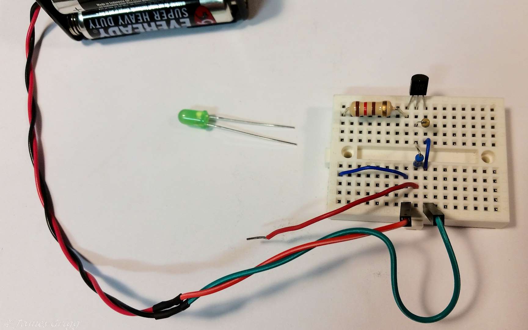
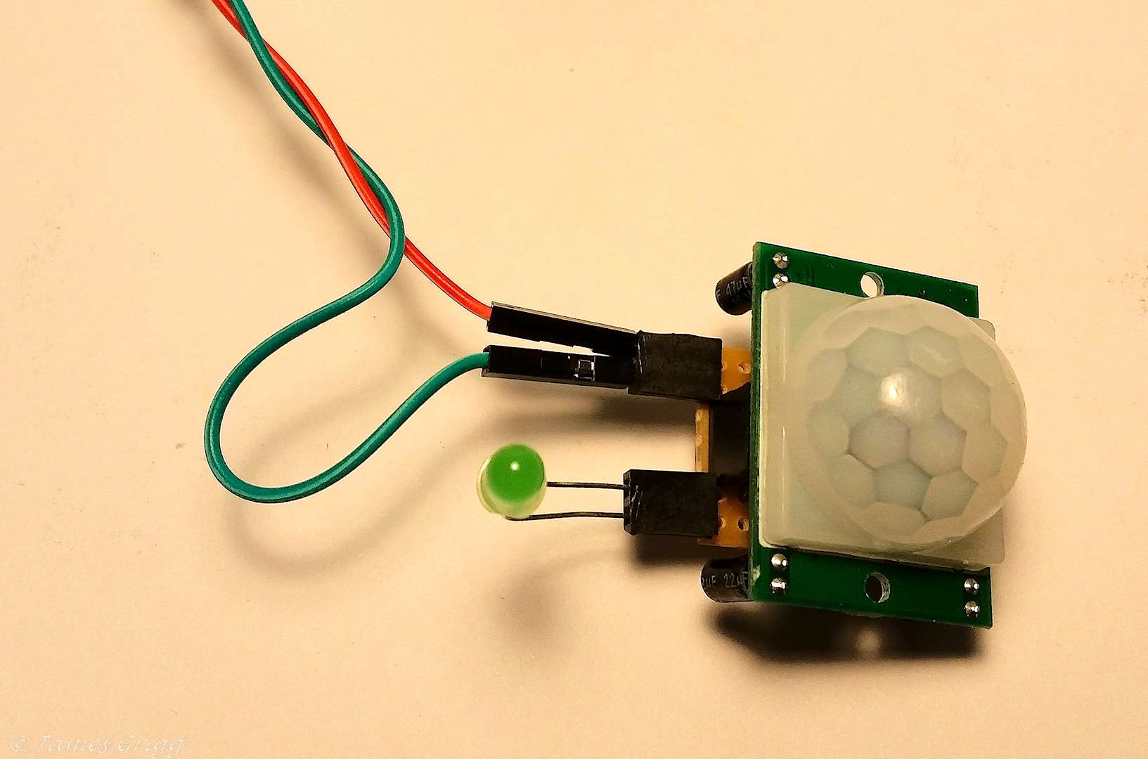
In circuit design and construction it is best to take it in stages, build one part, prove it works, then move on to the next part. Eventually you should have a small pcb board with all the parts soldered on it with leads going to the LED and the PIR. (depending on where you want to place them)
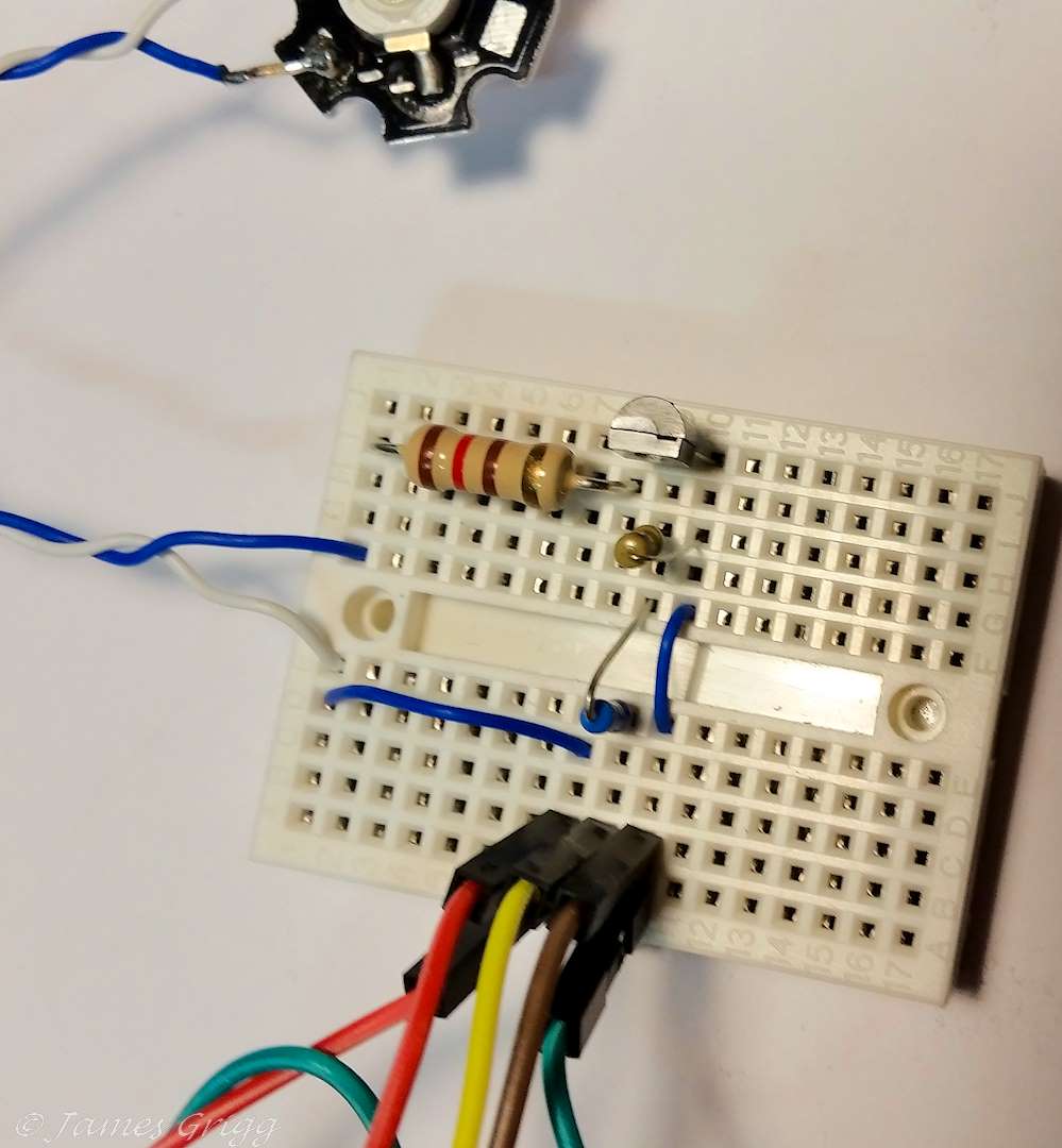
The battery pack you bought has two wires attached. The red one is + volts, the black one ground. In my pics the green wire to my battery pack is the same as the black one to your battery pack. I cut the leads on the components to a shorter length so they would not short out on the breadboard.
Cheers
Jim
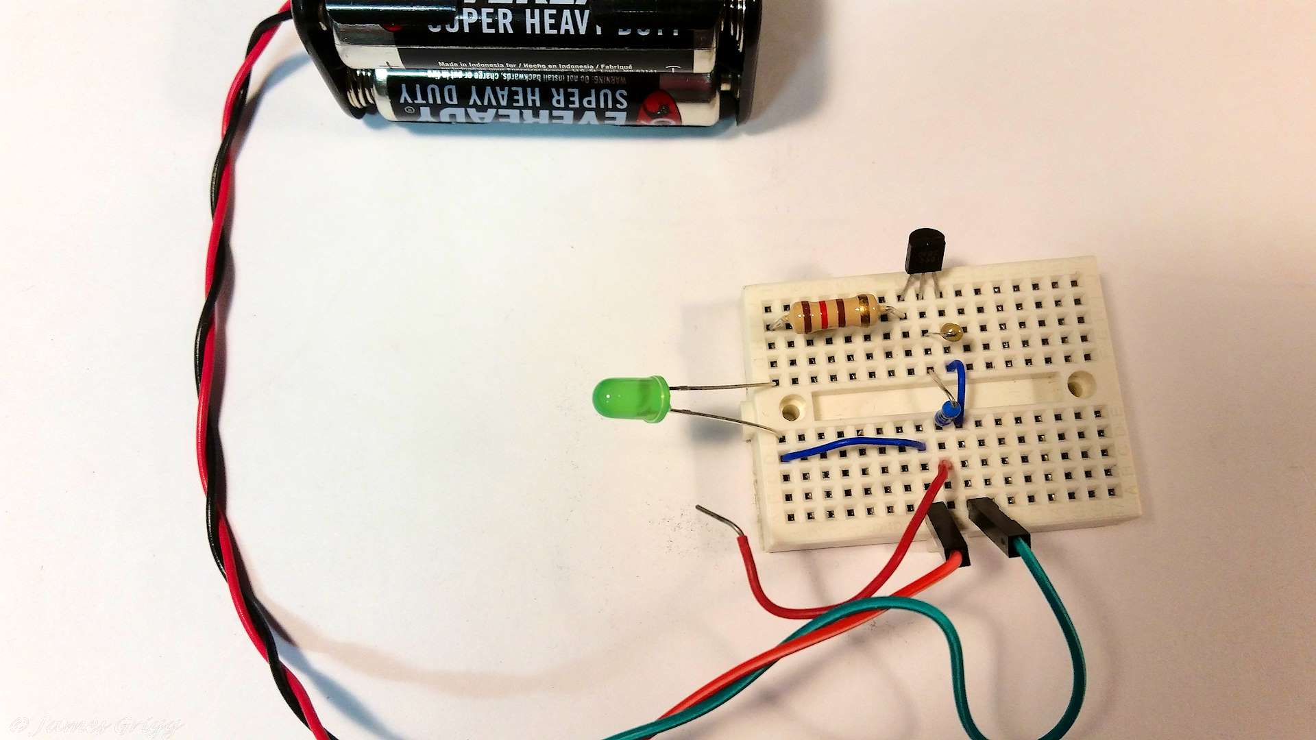
Once you have the transistor switching the light on and off, you can add the PIR. The red wire I used to test the transistor is no longer needed.
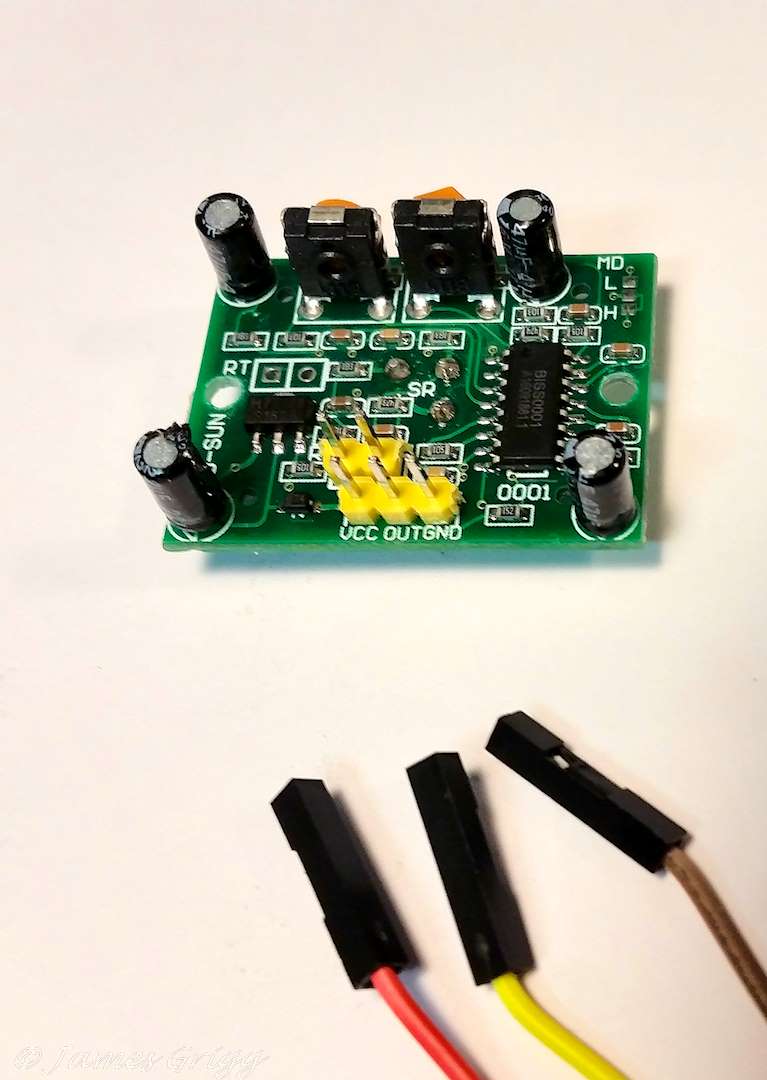
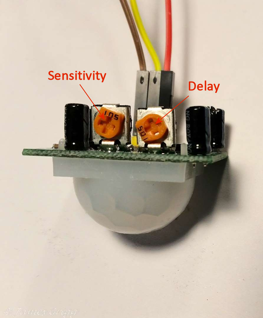
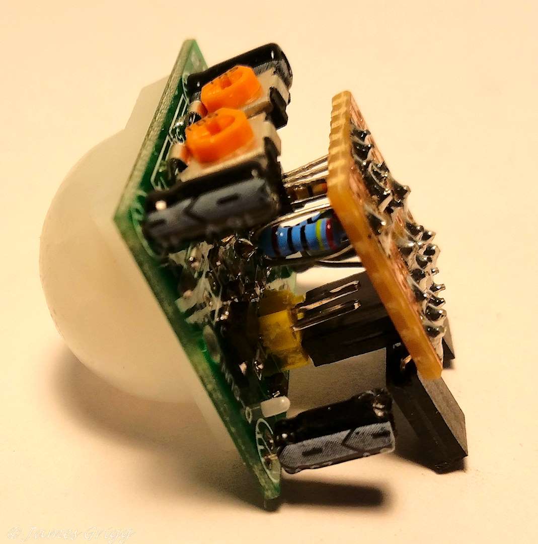
The PIR has two trim pots, one for delay and one for sensitivity. Adjust them as shown in the pic. This should give about 2 seconds on time and good sensitivity. Later you can adjust them for longer delay and different sensitivity to suit how you want the sconce to work. It is a little hard to get to exactly the second you want.
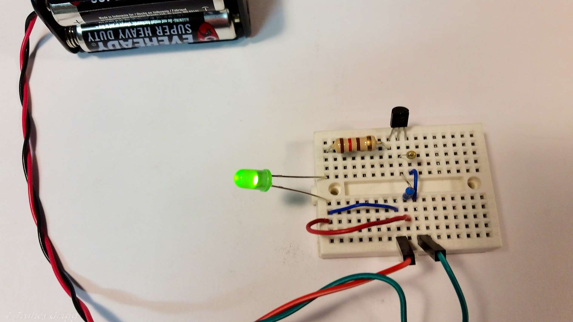
If it doesn’t work, check your wiring. If necessary remove the PIR and go back to the previous step to confirm the transistor still works.
Basically you now have the circuit working as you want. You could adjust the sensitivity and delay to suit your purpose. In the next post I will discuss putting it all on a small PCB.
Hope this is clear enough and is helping.
Cheers
Jim
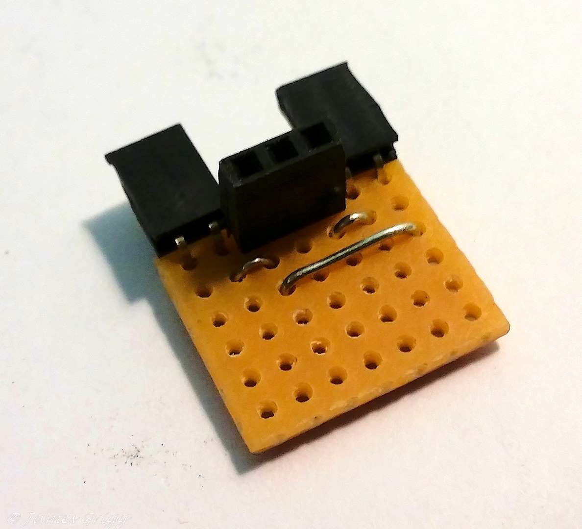
This post consists of building the circuit on a small piece of vero board and testing to show it works. Beyond this is up to you and how you want to incorporate it into your design. I am happy to provide whatever assistance I can via this forum for you to get it working as you want. This is just a suggestion, btw.
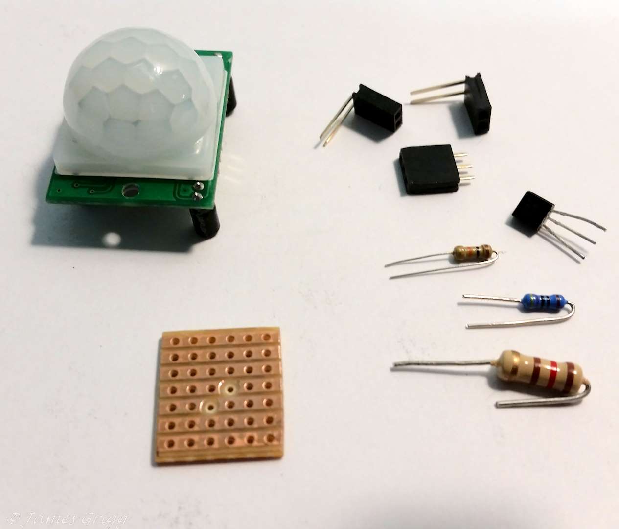
The vero board I used is not sold by Core Electronics; I purchased this from Jaycar and cut a small section out. The board is very easy to work with, has tracks that run the length of the board which can be cut with a drill bit, if you are careful.
https://www.jaycar.com.au/pc-boards-vero-type-strip-95mm-x-75mm/p/HP9540
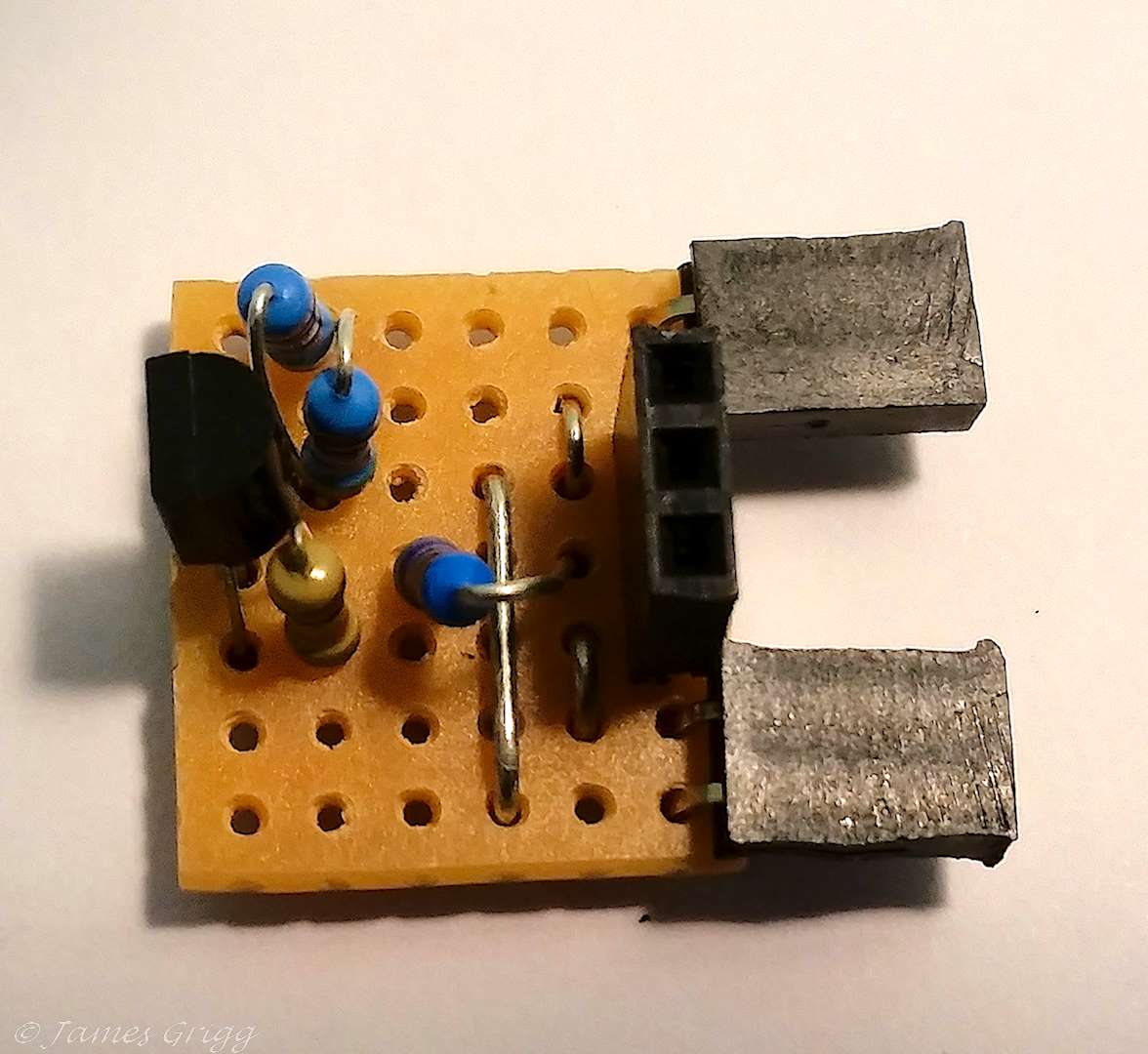
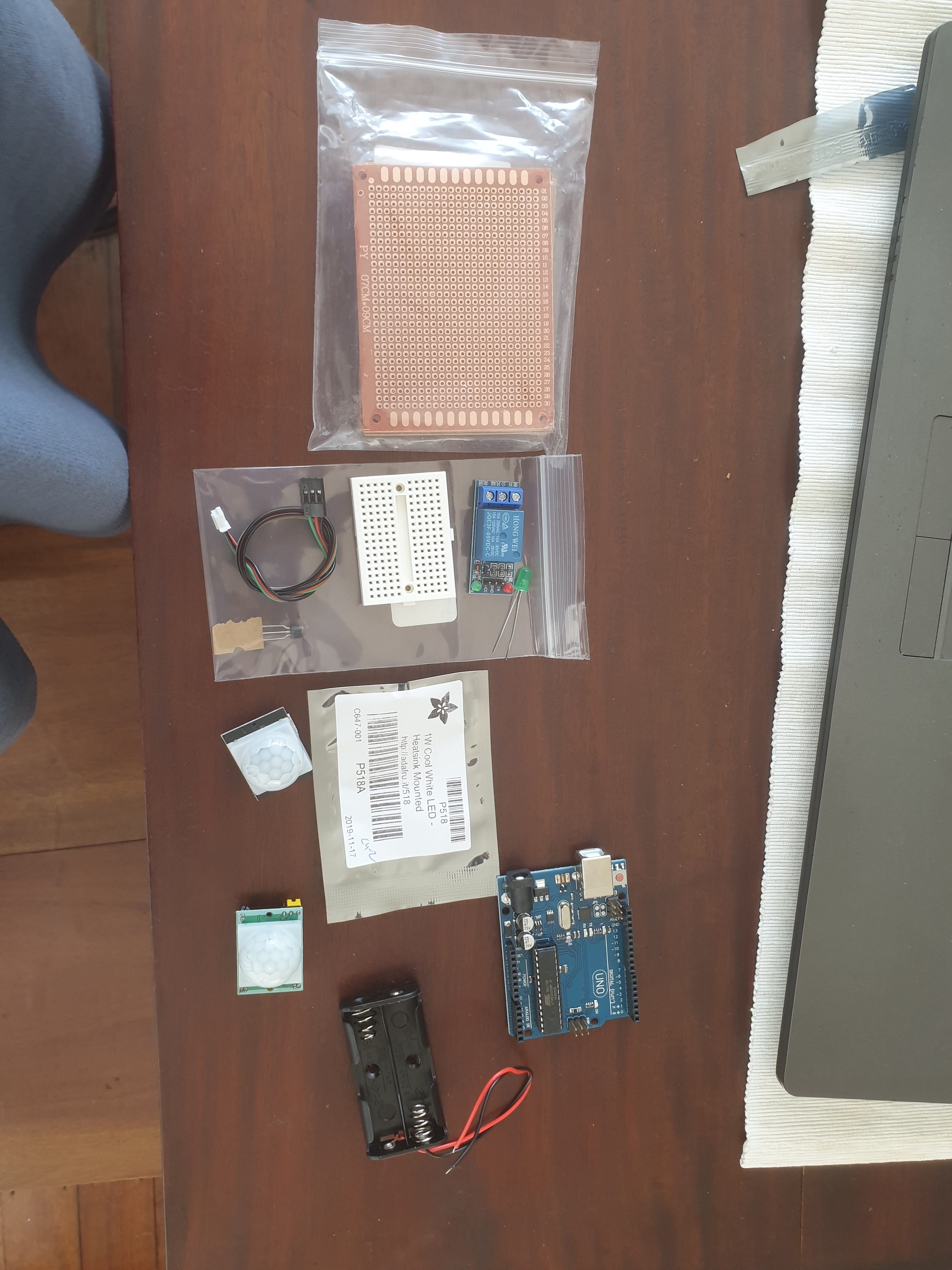
The following parts can be used to connect the PIR, LED and battery to the board.
The PIR has 2 small holes that can be used to mount in in a box or something, I used these screws.
All the best, and as I said happy to help.
Cheers
Jim
I dont have ANY electronic gear other than what I bought, no connectors, no wires no nothing.Can you provide a list for me to purchase?
Hey Joe,
Below I’ve created a list of parts that should be suitable. Have a great day!
Bryce
Core Electronics | Support
Hey thanks. That’s what is outstanding from the images?
Joe
Hey Joe,
You can probably do without the F-F connections, but other than that everything on the list (exc. soldering equipment) should be all you need to set your project up. All the best with it! Make sure to let us know how you go!
Bryce
Core Electronics | Support
Any chance you can bundle James “how to” in 1 document I can download?
Joe
Hi Bryce,
Thanks for providing Joe with the items he needs. I have been busy and intended to do this eventually.
Hi Joe,
I guessed from your comments that building anything would difficult due to lack of solder station, tools and parts, etc. That is why I choose the breadboard, it is easy to plug into and change things if necessary. But it is not reliable, it is just to prove a circuit works.
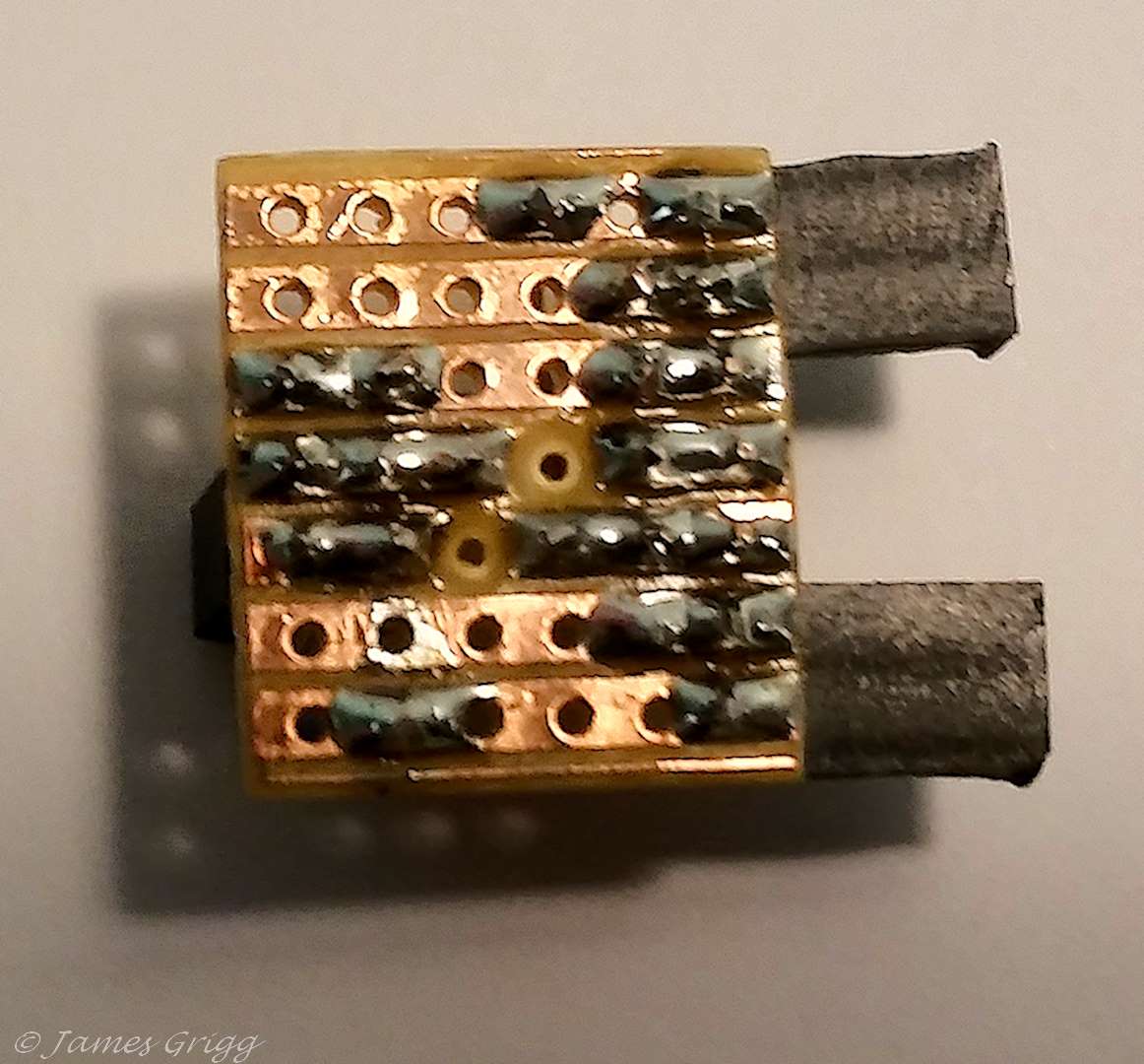
I built the circuit on a small piece of vero board to show you how small it could eventually be with the parts soldered on making it much more reliable.
I can put my “how to” into a pdf document, I will try to do that soon.
Cheers
Jim (Core Electronics Customer)
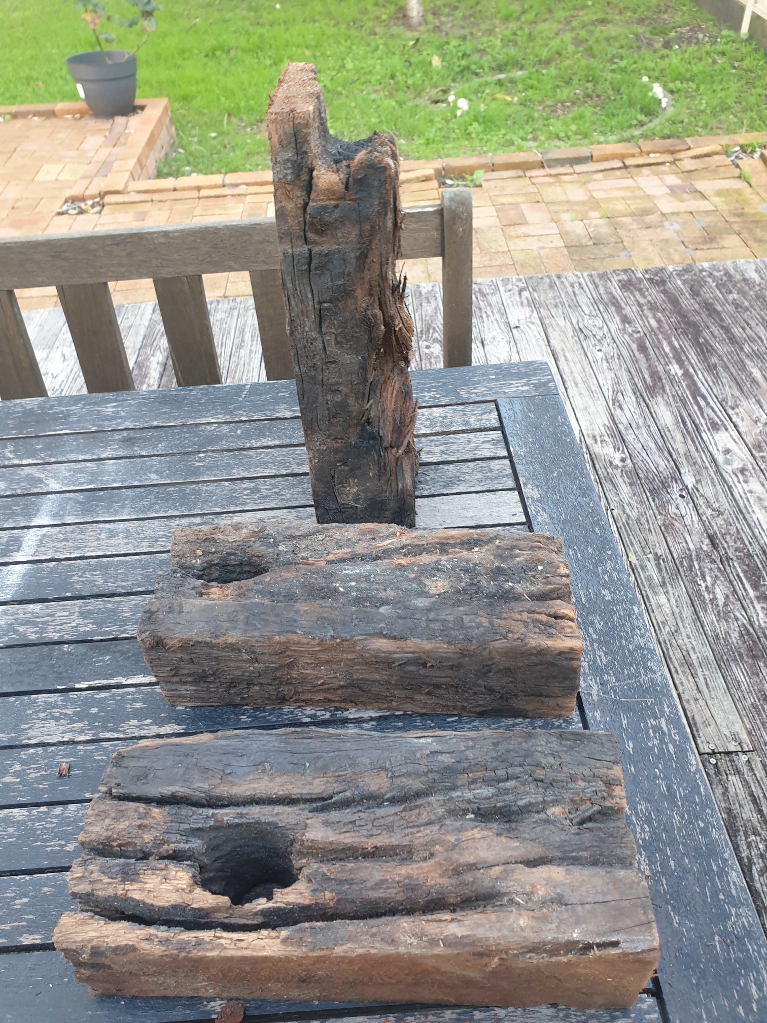
Hi Jim, I would appreciate the pdf. Here in Taree our jaycar people don’t know between a landline cable and network one so I am at a loss for help. Bought a soldering iron though. Frustratingly I have the wood…
Joe
Hi Joe,
Attached a pdf, this should help in your construction.
Cheers
Jim
Instructions - Part 1 Beadboard.pdf (923.4 KB)
Hi Joe,
Second part of the document, construction of a circuit board.
Enjoyed working with this circuit and producing the documents, hope they are of help to you.
Cheers
Jim
And you can get our latest projects and tips straight away by following us on:
![]()
![]()
![]()
![]()