I’d like the wiring & install of the flashing rain light to be as simple as possible because although I can solder, I am a complete newbie to all this electronics stuff - learning as I go!
Ideally the light should be powered off the receiver as suggested. Although it would be nice to turn the light on and off from the receiver, that’s not important. It can be either red or white as I have either colour in translucent PLA for the printed cover.
It would be good to have the flashing slow down or change when the Lipo battery is getting low. Again, not critical if it makes everything to complicated.
What I need help with is a list of parts including the wires/connectors I need (eg. between the LEDs and resistors and the resistors and receiver etc). Thanks in advance and…be kind.
We’ll get back to you on this soon, I’m just trying to figure out the best way to answer this. For now, I’d take a look at this project based on a 555 timer that should have some useful info for your project.
You’re right, that tutorial massively overcomplicates the requirements for such a simple application which could easily be put together with a microcontroller. You’re much better off writing a custom script to control the LED/s based on the inputs provided to a board such as an Arduino Pro Mini (or ) as they suggested on Thingiverse with a script you’ve customized to control the brightness with PWM (there are 6 suitable pins on the board), frequency of flashes, etc.
You can use a 5-12V battery to supply power to the Pro Mini (your 7.2V battery should do the trick). As for controlling the lights from your receiver (The GT2E), I had a look at the pinout, and you should be able to hookup an input from the Pro Mini to one of the channels to be able to let your script know when to turn on/off the lights or perform other actions.
You should be able to learn all the code necessary to set this all up in the free workshop below, let us know if you have any questions about it
Hi Bryce - what do I use to connect the Arduino to my computer usb for programming? I have the thing in my attached photo, but I don’t know what it is - would it help??
But how do I connect it to the Arduino? I don’t have a bread board
I have a Mac computer - not sure if that makes a difference?
Also, the cable I have(in the photo) has a female 2 x 3 pin adapter on the end. So the cable goes from 2x5 down to 2x3. I don’t get how to connect either of those the the 1x6 header of the Arduino
is that the only board you have as the unit that you show there is the debug board for the audino nano and alike…which i assume you have or need to purchase for the project…all you need is an aurdino and a usb cable to fit …i think just a flashing led and a battery may be an easier alternative…
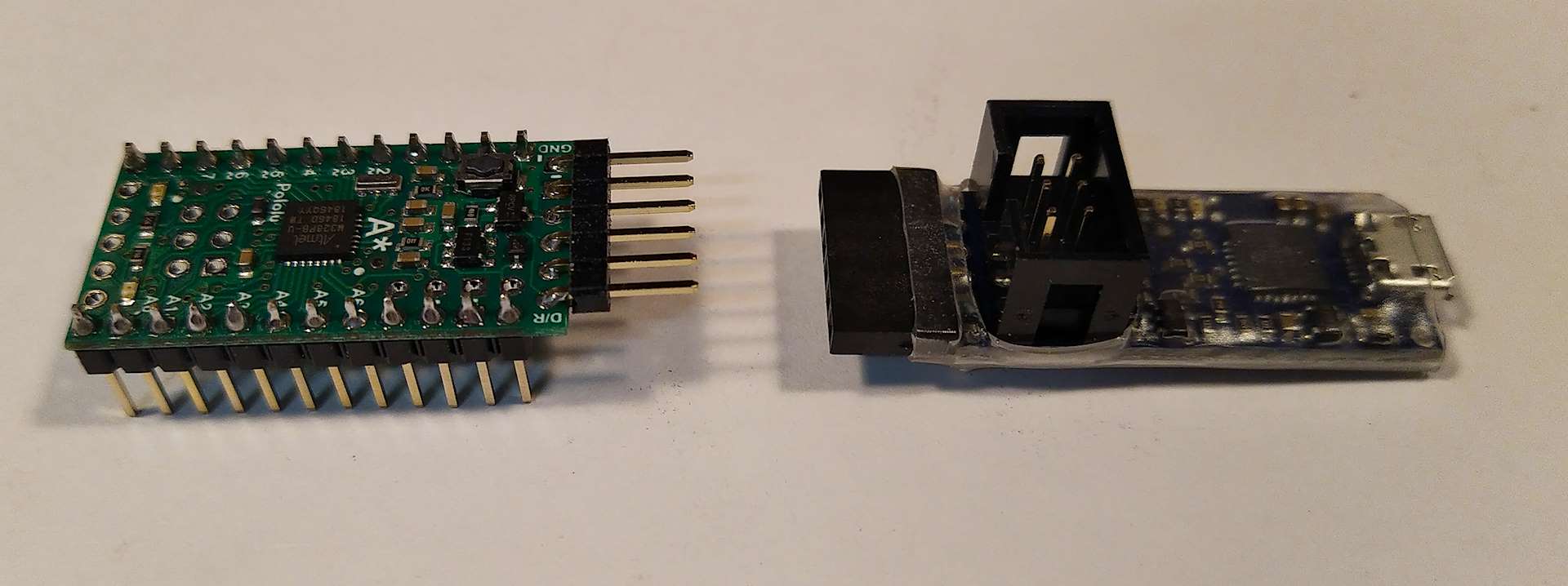
The device in your pic looks like a USB AVR programmer, it can use the MOSI MISO interface of the Arduino to load code into the microprocessor. It is a lower level programmer that will over write the boot loader of the Arduino. It can brick the Arduino and should not be used if you are new to programming the Arduino. (personal learning experience)
Recently I purchased a POLOLU-3172. This has both the types of programming interfaces. The 6 pin serial interface is the one to use. It uses the TX & RX pins to load the Arduino with code. I have recently used it to load code into a A-Star 328PB micro, POLOLU-3162. Pololu have excellent instructions for getting these two devices to work. The programmer will work with any Arduino micro.
Pololu have a configuration application that will allow you to make changes to the setup of the programmer. The default setup will generally work in most cases. The programmer can provide power to the Arduino but the default setting is NOT. Therefore it is necessary to provide power to the GND and +Bat pin of the A-star to get it to work or similar for other Arduino’s. The programmer auto detects 5V or 3.3V micros.
Loading code via the TX & RX lines, using the bootloader installed in the Arduino, is the easiest and safest way to program the micro. It is similar to how the Arduino UNO loads code.
All the best
Jim
Originally, I only looked at the programming device in your pic. And provided an answer to your question about what it was and how to use it.
I have now looked in more detail at what you want to do. The Arduino code looks for a greater than 1.7msec high pulse from the receiver, turns the LED on for 200msecs then off for 200msecs. Then it checks for the pulse again and repeats. This makes a micro ideal for reading the pulse and controlling the LED.
I have thought of a number of scenarios but cannot come up with a circuit to just connect the LED to the receiver and have it blink nicely. Connecting the LED directly to the receiver pin; probably would not work as this pin would not be designed to provide this type of power and the LED would blink at a rate that the human eye could not see and just appear dim. (25msec)
Can you provide information on the Arduino you are using ??
Pic maybe. That will help me in determining the easiest way to program it.
Thanks for taking the time to help me. I haven’t bought the Arduino yet, but the thingiverse page suggests the Arduino Nano or pro mini. So I think this one? https://core-electronics.com.au/arduino-pro-mini-328-5v-16mhz.html
But what I can’t work out is how to connect it to my computer (Mac Catalina) by USB in order to upload the code provided. I have seen this on another store: Arduino USB to 6 Pin TTL Serial Converter Module do you have something similar? If that’s ok to use, what pins to I buy to attache to the Arduino so I can connect the two?
Honestly, any Arduino device will work, it does not have to be a Nano or Pro Mini. In my opinion these are over priced for what they do. (started to write a big post but decided it might confuse)
In my post above I linked the A-Star 328PB 3.3V 8 MHz board and programmer. The programmer will work with the Pro mini. It connects to the 6 pins at the top of the board. You would solder a 6 pin connector to these pins and plug in the programmer. The Pro Mini comes with the Arduino IDE the A-Star does not but can be added pretty easily. The 6 pins at the top of the A-Star board are the same as the Pro Mini.
Do you have the Arduino IDE installed on the MAC ?? If not you will need it.
Decisions; decide which Arduino device you will get. Pro Mini does the same job as the A-Star but is more expensive. The Pro Mini board is listed in the Arduino IDE, the A-Star needs to be added. Both have a similar footprint. Both will work with the battery you intend to use. Both can use the programmer to load programs.
Anyway, the Pololu programmer is an excellent device and easy to get going compared to other programmers I have used. I highly recommend it.
Regards
Jim
PS
This is just a serial device it cannot be used as programmer.
Yep.
The receive output is a pulse, greater than 1.7ms within 25ms. You would need a circuit to retrigger on pulses to keep the LED running. It could be done. 555 timer could do it, me thinks. see Bryce post above. Don’t think Melissa wants to go that way, by the subsequent post.
Hi Guys - thanks so much for all your help! I’ve decided to go ahead with James’ suggestion and have ordered the board and programmer and other bits and pieces this afternoon. Hopefully they won’t take too long to get to me so I can get this thing done!
Some links to get you going.
Pololu AVR Programmer V2.1. User guide and MAC installation package.
If you bought the A-Star 328PB 5V 16Mhz micro. User guide for getting it working and installing the board in the Arduino IDE.
If you bought the Pro Mini its board definition comes with the Arduino IDE.
Suggest getting the programmer working with the Arduino IDE first.
Then solder a 6 pin connector to the micro. Carefully as the boards are pretty small. I use the finest tip I can find for the soldering iron.
You could then run the programmer utility and set it to output VCC, this will power the micro board when you connect it. So all you need is the programmer and the micro to load code.
The onboard LED on digital pin 13 can be used to prove it is loading code and working. I usually modify the time in the blink program. Fast or slow blink.
When you are confidence the board and programmer are working and you can load code ok, you could look at getting the receiver input to work. I use the Serial.print() function to debug the code. On the top right of the IDE there is a an icon that when clicked will open a serial monitor.
Apologies if you know all this already.
Hi James - I’m baaaaaack!
The board etc has now arrived and I’ve finally had a chance to review and get a little bit more familiar with things. I’ve managed to solder the header onto the board. The only problem I have now is that the wiring diagram provided by thingiverse uses the Arduino Pro Mini board and the A-Star I have bought looks different. So I am not quite sure if I have the correct holes for the correct wires so that the code (provided by thingiverse) is all ok.
I’ve attached a copy of the wiring diagram as well as a photo I have marked up the way I think it should go together. Would you mind checking to see if I have it right in my photo?