Hi Dennis,
Could you share a picture of your setup?
Hi Dennis,
Could you share a picture of your setup?
+1 to @Jack 's request for a picture.
I’d like a link to the video you followed. ![]()
https://youtube.com/shorts/8LrlBVnIKxc?feature=share link to my video
https://www.youtube.com/watch?v=MRN2b34enEk&ab_channel=ABTabi link to video I followed for 555 circuit (I followed the first section for delay on). Youtube automatically made it into a short annoyingly.
Hi Pix and everyone
I think the timing capacitor and resistor are reversed. Change places (Cap pin 2 to ground) and resistor pin 2 to VCC.
Cheers Bob
Add on
You might need a high value (1MΩ???) across the cap, pin 2 to ground to discharge the cap once the power is removed. Otherwise it might only work once.
Hi robert, please refer to my video to see the issue. I followed a tutorial (2nd link) but it is acting in a reversed mode (see link 1). Have not had the issue of the discharging but I will implement it if needed.
I had that problem recently too. So weird.
Good to see the problem. I noticed the mp3 player light coming on a few moments after the board. That would cause a pop for sure.
Unfortunately I can’t pause the video to get a good look at the wiring of your board.
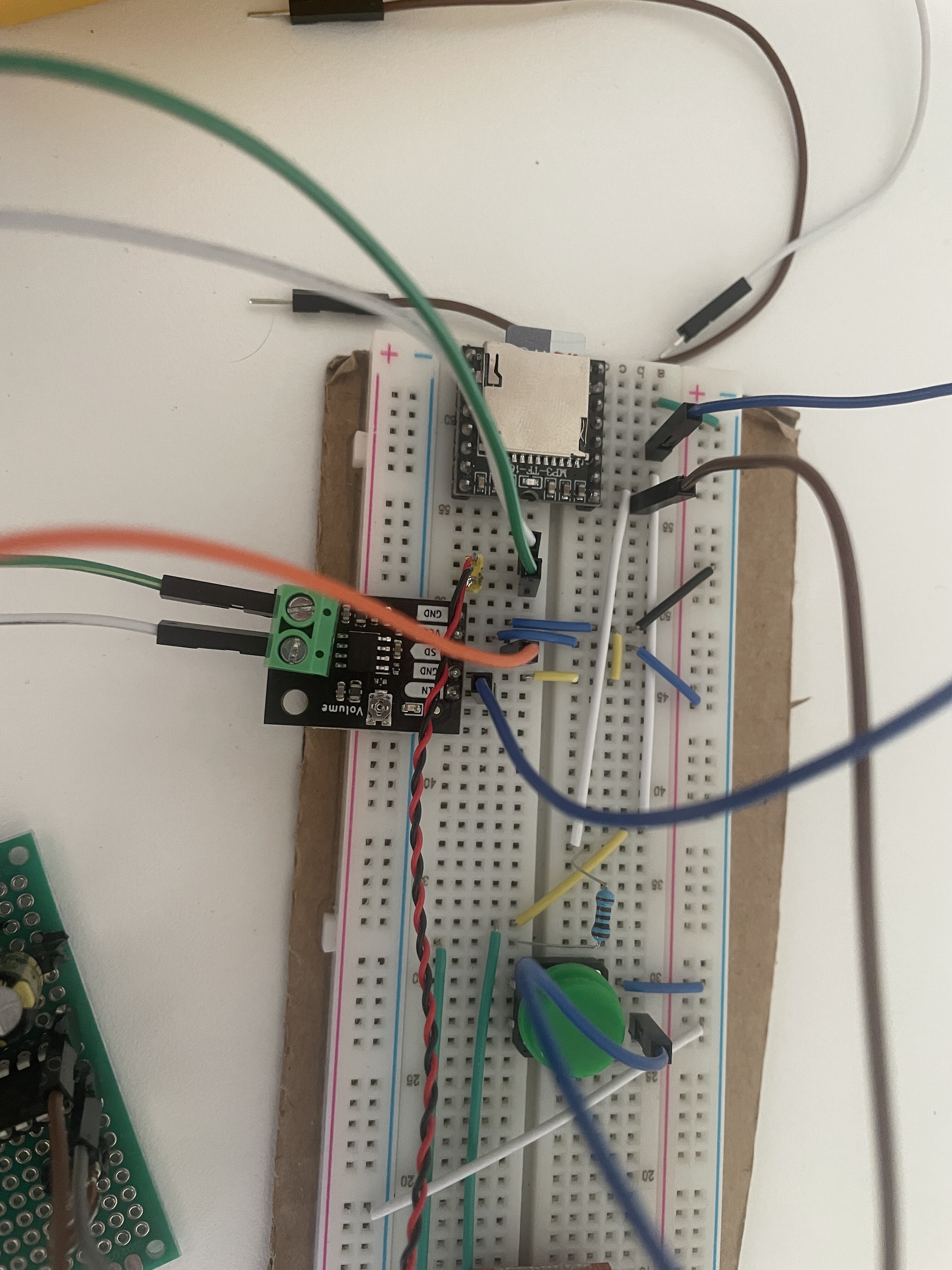
Could you take an up-close still photo for us so we can get a better look?
of which board the ne555? The mp3 light only comes on when a file is playing.
Yeah the ne555. ![]()
makes sense
Did I mark the pinout on this correctly?
Did I mark the polarity of this cap right?
Does that mean that the negative side of your capacitor is connected to pin 8?
I think your cap might be backwards my dude ![]()
The cap is connected to pin 1 and 2. The negative side to 1. Is the incorrect?
Nah man.
The positive cap goes to vcc.
The negative goes to pin2.
I see, I am still unsure if this is the issue as I just put a led - leg instead of the mute pin and it works correctly, off for x time then the led turns on.
I’ll give it a go tho, everything else is ok right?
Hi Dennis
Just did look at that video. What part of “Reverse position of timing resistor and capacitor” did you not understand.
That second video clearly shows the capacitor connect between pin 2 and pin 1 which is ground. That is the correct position. If that is an electrolytic positive side goes to pin 2.
Do that and it might work with a bit of juggling component values. If the required hold off time is known these values can be calculated.
In operation at switch on the cap is a short circuit so pin 2 will be at ground. Pin 3 will be high (Amp off). When pin 2 reaches 2/3 VCC pin 3 will switch LOW whichI believe will enable the AMP and switch it on.
I think that is what you want
So just reverse these 2 components from the positions in Pix circuit and it just might work.
Cheers Bob
I am a bit confused re the action of the Mute. Is the Amp muted when this pin is high or low.
If Low this is going to be reversed. If I get a chance I will try Pix’s circuit in the next few days and see if I can make any sense of it. I know it is not the normal way to connect the timing components. You will still have the cap discharge problem I think.
Edit: Just checked the data sheet. Low is Amp Off, High is Amp ON so the 555 is reverse to what you want.
I will have a look at my 555 bible and see what can be done.
I see this is my current issue. The amp is muted at LOW, so indeed it would need to be reversed. LOW on startup then to HIGH at 2/3.
By reversing do you mean switching the capacitor to the resistor’s spot or reversing polarity
Hi Dennis
Yes, The capacitor needs to connect from pin 2 to ground (Pin 1) If it is an electrolytic the positive side to pin 2.and the resistor from pin 2 to pins 8 & 4 (VCC).
You say you have a couple of 2N2700s. You can use one of these to invert the 555 output. I will come up with a simple circuit that should work for you and post tomorrow.
What sort of time delay do you need and I will try to advise some values.
Cheers Bob
Yes i have 2x 2n2700. I have several trimpots to adjust the values would that work? 200ohm, 1k, 20, 50k, 100k. Looking for 1-3 seconds delay.
Dennis
1mΩ and 1µF will give you 1.1Sec. 1MΩmight be a bit high so I would work on 100kΩ and 10µF for 1.1Sec.
!00kΩ and 27µF should theoretically 2.97Sec so you could work from there.Somewhere in between. Component tolerances and circuit strays might modify this but I don’t see the actual time being critical.
Will post a circuit including a 2N2700 tomorrow.
Cheers Bob
Hey @Dennis273978
I think the video you followed was just a little heavy to follow.
Are we deviating away from the design from this video?
On after delay circuit
I’ve made the circuit from that video and it works amazingly.
Was there something in the video you need clarity on.
That being said if @Robert93820 recommends a circuit that works for you go for it.
Bob knows his stuff.
Hi All
Just had a look at Pics circuit along with the video he used. I have never seen the timing components connected like that and it just looked wrong. I have just had a quick look through my 555 bible and could not find that arrangement anywhere , all have the timing cap between pin 2 and ground.
But, after some thought and video confirmation I can’t see why it would NOT work. Well done Pix I intend to try that for myself. The same timing formulas would apply, just happening the other way around.
The only thing I can see that would be likely to give trouble is the SD input to the Amp has a pull up resistor fitted which may allow the Amp to switch ON until the output of the 555 can go low. The output of the 555 is an OpAmp which DRIVES the load High or Low so there may be a conflict here. The one shortcoming with a 555 is the time delay between input and output which may allow the Amp to come on.
There may be a way around this I will think again tomorrow with a bit clearer head. I may have to do some timing checks with a 555.
Cheers Bob
And you can get our latest projects and tips straight away by following us on:
![]()
![]()
![]()
![]()