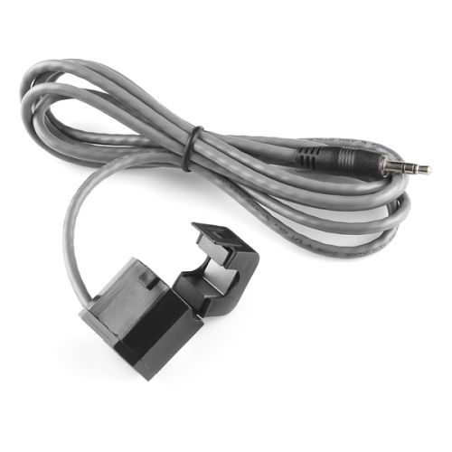
This non-invasive current sensor (also known as a “split core current transformer”) can be clamped around the supply line of an electrical load to tell you how much current is passing through it. It does this by acting as an inductor and responding to the magnetic field around a current-carrying conductor. By reading the amount of current being produced by the coil, you can calculate how much current is passing through the conductor.
The data sheet for this device specifies a maximum of 60A so it should handle your max of 45A OK. There is a figure for accuracy and linearity with a 10Ω load resistor which according to the published graph produces an output across this resistor of 300mV at 60A. The ratio of through current to output current is 30A / 15mA. I suppose you could adjust the value of this resistor to suit your measurement range. The specs are only quoted for a 10Ω resistor but I don’t think increasing it a bit would do much. Don’t go too far though or it probably would make a difference. Probably safer to use an OP Amp to adjust the output to where you want it to be.
Cheers Bob
Hi Jeremy
Forgot to welcome you before. Welcome.
I just deleted the last post. It was mainly completely incorrect. new version.
I have been doing lots of thinking about this device and similar situation I had many years ago (it was RF but the principle is the same) which I will briefly describe later.
Consider this
You have a transformer with a single turn primary and at this stage an unknown turns secondary terminated with 10Ω.
Now a terminating resistor on the secondary will be reflected back into the primary with a value relating to the square of the turns ratio. Going from the low turns side you would multiply the low side impedance by turns ratio^2 and going from the high turns side to the low you divide the high side termination value by turns ratio^2. Thus with a 1:1 transformer the resistance seen at the primary is equal to the resistance terminating the secondary.
Determine the turns ratio. From the data sheet 30 A primary = 15mA secondary. I make this 2000:1
The secondary termination is 10Ω so the reflected impedance to the primary will be
10 / 2000^2 or 4,000,000 which is very low but will appear as a resistance in series with the primary. While this resistance is very low in this instance IT IS THERE. This is quite important as will be demonstrated below.
To my dilemma of quite a few years ago.
25W SSB transmitter. Problem no output power. Won’t go into fine detail but I could find nothing wrong. The front panel power indicator lamp was out but with no power I did not expect it to be on.
Fortunately I had access to the engineer who designed this thing. He asked if I had checked the incandescent indicator bulb. No I had not.
Result, bulb blown, replaced and lo and behold unit worked perfectly.
Egg on face. The reason. This was a coil of many turns wound as a core and was fitted around the antenna feed wire, similar to the present situation. With the open circuit bulb this was an open circuit or infinity reflected back into the one turn primary resulting in a very high resistance (open circuit) in series with the antenna wire. Result no output power.
This is one of the lessons one tends to remember.
Getting back to this discussion. UNDER NO CIRCUMSTANCES operate this device WITHOUT the 10Ω termination. I would not predict the outcome but if it has anything to do with mains circuits the result could be spectacular. OR nothing might happen at all except for nil or very low volts getting to the destination. I am not going to try it to find out but think about it and be careful.
Hope this helps and sorry about the post I just deleted.
Cheers Bob
Thanks Bob.
My use for this is a line side I/O monitor for my solar and controlled load. Thankfully I have a reference for expected values due to it being monitored via an app.
Why 45A? Because ausgrid have upped the solar output limit per phase to 10kW.
The plan is to put one of my pi3’s to good use as a power monitor/logger.
I really wasn’t expecting such a detailed response, so thanks again.
Cheers, Jerome.
Hi, I need help with this thing…Seems it should be simple, but, I am not an EE! I just want to detect when a domestic pressure pump is running. Got a test setup with the active split out… but there seems to be no documentation about earth/ring/tip…which should be used? And what load resistor? I started out with 12 ohm… just because I had one. Putting a CRO across the tip, ring and earth shows some very weird waveforms… and frequencies! Also tried making a half-wave rectifier with a IN4004 in series with said 12 ohm (also tried 100 ohm… that failed, I guess too high?) … things just got more confusing!
I am running my test on the bench with a 1kW blow heater running to simulate my pump. Still fairly low amps, but should surely be easily detectable??
Bottom line is… I just want a reliable voltage I can read on my Pico… pump running… or off.
Any help appreciated! Suggestions re alternate sensors welcome…
Your 1kW heater will be drawing about 4A Also the output from this device will only be about 20mVAC.
Do NOT use any other load resistor other than 10Ω. read my previous posts above for reasons.
The diode is in the wrong place if in series with the 10Ω resistor and anyway it needs about 700mV to turn on so even at 60A this would not operate. Probably you are seeing strange pics on the scope.
I would look at some of the Hall effect devices. Minimal circuit disruption at only a few mΩ. These will give an AC voltage output relative to AC current centred around half VCC. Look at the data sheets. They are your friend. I think Core stock some of these already mounted on break out modules in varying current capabilities.
Cheers Bob
PS: If this set up is associated with 240VAC GET AN ELECTRICIAN.
You might be better off investigating a lower voltage pressure switch or detector. Then you might need a plumber.
Yes. DO NOT USE without the 10Ω load. See above for reasons.
Cheers Bob
Be aware the ground clip on the scope is probably connected to mains earth unless it is battery operated and the case is floating.
Hi trevor
Well I finally found out what a “SS101990059” is. It would be a great help in the future if you could provide a link or a Core product number as at first glance this description means absolutely nothing.
After looking at this data sheet please disregard the “Yes” above re tip and ring connection. This one has connection to tip and sleeve apparently. I was only going by audio convention. Chinese logic perhaps. Anyway you have only 3 connections, find out for yourself, you should be able to measure the coin resistance across 2 of them.
Back to this product. The Core page has a couple of useful links. One to the data sheet which doesn’t say much. Another refers to connecting to an Arduino which is much more informative and should supply all the info you require including the offset applied to get the AC signal all on the positive side of zero volts and how to do it. There are also calculations for 3.3V systems if needed.
Remember DO NOT just clamp this device around a complete mains cable. It MUST be around 1 wire, either active or neutral, but not both.If around both they will cancel and you will see nothing.
What you do with this level shifted sine wave signal when it gets to your controller is up to you
Cheers Bob
PS. In reply to your original question. Yes this one would be better as it is a lot more sensitive. Max 10A compared to Max 60A.
As interesting as this discussion is … can i get back to the SEN-11005 ?
I currently have a powerboard in my laundry with 3 smart power plugs to let me know when the washing machine and dryer have finished, and that the freezer is still running. Another one has failed, and I have bought an Athom no-relay plug to replace it (which will hopefully last longer). But, maybe there is a better alternative ?
The only smart powerboards I have been able to find measure only the total current - I guess that manufacturers don’t see enough of a market for such a device … and so I’m wondering if its feasible to make one.
I’m not worried about the measurements being accurate - just whether it’s time to go downstairs to the laundry because the washing has finished. Similarly there is no reason to switch the appliances on/off.
I understand that these clamps are the appropriate way to measure 240v mains power - which will mean either mangling the power cords of the 3 appliances to add clamps there; or building three clamps into a custom power board.
Or is there a simpler or neater way to measure 240v current ? I’m not sufficiently into soldering or electronics, so would be looking for off-the-shelf modules.
And yes, i am well aware of the dangers of “playing” with mains voltages.
Hi @Donald23173 , glad you are finding this discussion interesting… it has been a long journey!
These clamps are fairly chunky… I don’t see it being feasible to build them into a custom power board unless you are happy with a fairly large box..MIne is 58x36x21 mm. If you find a smaller one… let me know!
I don’t know a simpler/easier way to measure 240V current (other than a portable clamp meter), but I take it you want something more permanent.