I am using a Peco Smartswitch to turn points on train set Can I use a Optocoupler 5v in and use a new 5v out The Peco Uses 5v com To Gnd at photo Top poto bottom is the set as on train set in test
1 I am looking to boost the signals current capability from the Peco to drive a signals to the Arduino with Dcc++ on it with jmri on the PC reads the signal Active or inactive
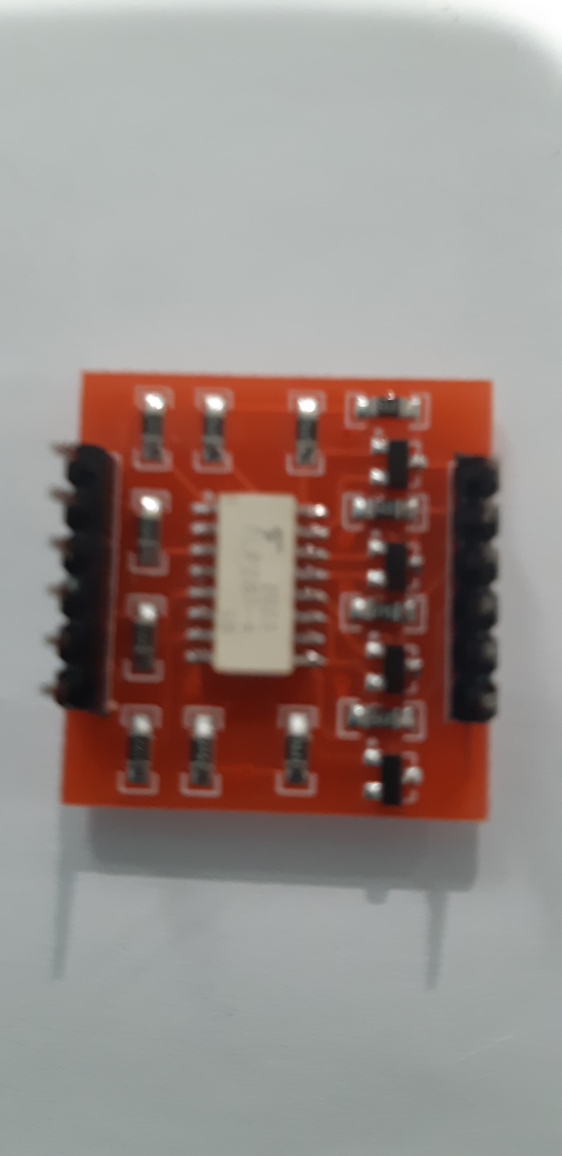
2 Photo bottom show the test unit using a Optoisolator 4ch but I can only use 1 Ch for the 5v + is com on the Peco
Smartswitch Manual v2.pdf (1.0 MB)
4 Likes
Hi Ray,
Welcome to the forum!!
A couple of questions first.
Do you have a link to the Peco switch?
Were you looking to boost the signals current capability from the Peco to drive some motors or servos?
A whole system diagram along with the intended functions of each module will also get everyone on the forum primed as to what you are trying to achieve with your project 
PS: optocouplers provide isolation between circuits at a specific voltage, kinda works like a torch and solar panel, great for sending through signals but cant output a lot of current, you can use a MOSFET or relay(if you arent switching too fast).
Here’s on that Core stocks, from the datasheet it mentions that it can output about 50mA/channel
3 Likes
Hi Liam
Thank you for the welcome
I have posted reply
Ray
3 Likes
Hi Ray,
I think I understand a little bit better, so you were looking to have the Peco send signals to the Arduino based on what gates are open?
Yeah an optoisolator will work perfectly here, it might be worth grabbing one of the DIP socket ones above as the manual says there are already current limiting resistors on the Peco, though the breakout board you have should work fine!
On the isolator breakout there will be the two sides, you dont need a common ground between the Arduino and Peco. On the input side (Peco) there will be a GND or COM which is the ground, then all of the R1G, R2G signals go into the inputs (IN pins on the breakouts I’ve used).
On the output(Arduino side) you will need to hook up the 5v power pin, the Arduino’s ground pin and the digital pins that you want to use. PS: on most breakouts there are logic level converters attached
2 Likes
Hi Liam
Input side of Peco is com is one only +5v to R1 are gnd on the peco ,who do I rev. the + to - on the
2 Likes
Hi Ray,
Could you please post a couple images of the front and back optocoupler that you have closer up?
The output that would usually drive the LED’s doesnt require a +ive voltage rail as the signal itself can drive the diode side of the optocoupler (Just IN and GND), the output requires a +ive and ground(Vcc, GND) voltage to provide the output as there is an amplifying transistor.
I’d also take a read over on Circuit digest as to how they work in theory: What is Optocoupler: Its Types and Various Application in DC/AC Circuits
3 Likes
Hi Liam
Upload is best to build a new unit with a opto no resisters on Peco side and resisters on the arduino side
Ray
2 Likes
Hi Ray,
It should still work.
On the NC side you connect the RxG(Peco) pins to the inputs( Optoisolator INx) and COM(Peco) to ground(Optoisolator GND).
On the out side, HVcc goes to the Arduino 5v, HGND to Arduino GND, and the ouputs to the pins you wanna use.
2 Likes
Hi Liam
It only works with NC side R1 to gnd Opto and Com Peco to input Opto
I have all tha above, I will look at building cir,with ?
Ray
4 Likes
Hi Ray,
Could you draw something up? An optocoupler is only capable of moving signal from one board to another much like a diode, you could also try and use a multimeter to read the output voltage, then bring them directly into the Arduino (some current limiting resistors might be required).
3 Likes
Hi Liam
Peco com reads 5v The gnd reads 0 v off and 2.84 v on with leds
Ray
3 Likes
Hi Ray,
Aaaaaahh I get what is happening now, they are hooked up like a bus, so the buttons ground the whole rail and for the LED’s there are some resistors in between. Unfortunately your optocoupler isnt setup in the correct configuration but with an LED connected across the RxG and COM pin you will be able to feed the signal straight into the Arduino.
https://learn.sparkfun.com/tutorials/logic-levels/ttl-logic-levels
2 Likes
Hi Liam
Thanks if I use a Bi-Directional Logic Level Converter BOB-12009 , The arduino is only reading pins High or Low
Ray
3 Likes
sorry Liam about the drawing but like this setup
5 Likes
Hi Ray,
I dont even think you will need a logic level converter for something like this, the 2.8V is read from the Arduino as a HIGH state so should be all good to feed straight into it, just make sure you are completing the circuit with the same LED’s that you have (they also clamp to a known voltage once the circuit is on from what you sent through before).
A logic level converter is used when there is a 3v system like an RPi Pico and it needs to send a 5v singal like an Arduino or WS2812’s.
3 Likes
Thanks for all your help will try the about and let you how it turn out
Ray
2 Likes
Hi Liam
I have tri all of about it still not working,
But Ihave used a Relay 5V low trigger and it working the V form Peco pin is 4.45V and still showing in JMRI
This relays OK to use in banks of 4
Ray
2 Likes