Afternoon,
I have a project I am working on to remove water from my house when it rains a lot using a pump and creating a python action to remove surface water. I’m looking to use a Pi Pico 2 and a Grove - Water Level Sensor (10cm) for Arduino I just have some questions about the sensor.
-
The water I am reading may contain soil and maybe not clean water. Will this sensor read accurately in this scenario?
-
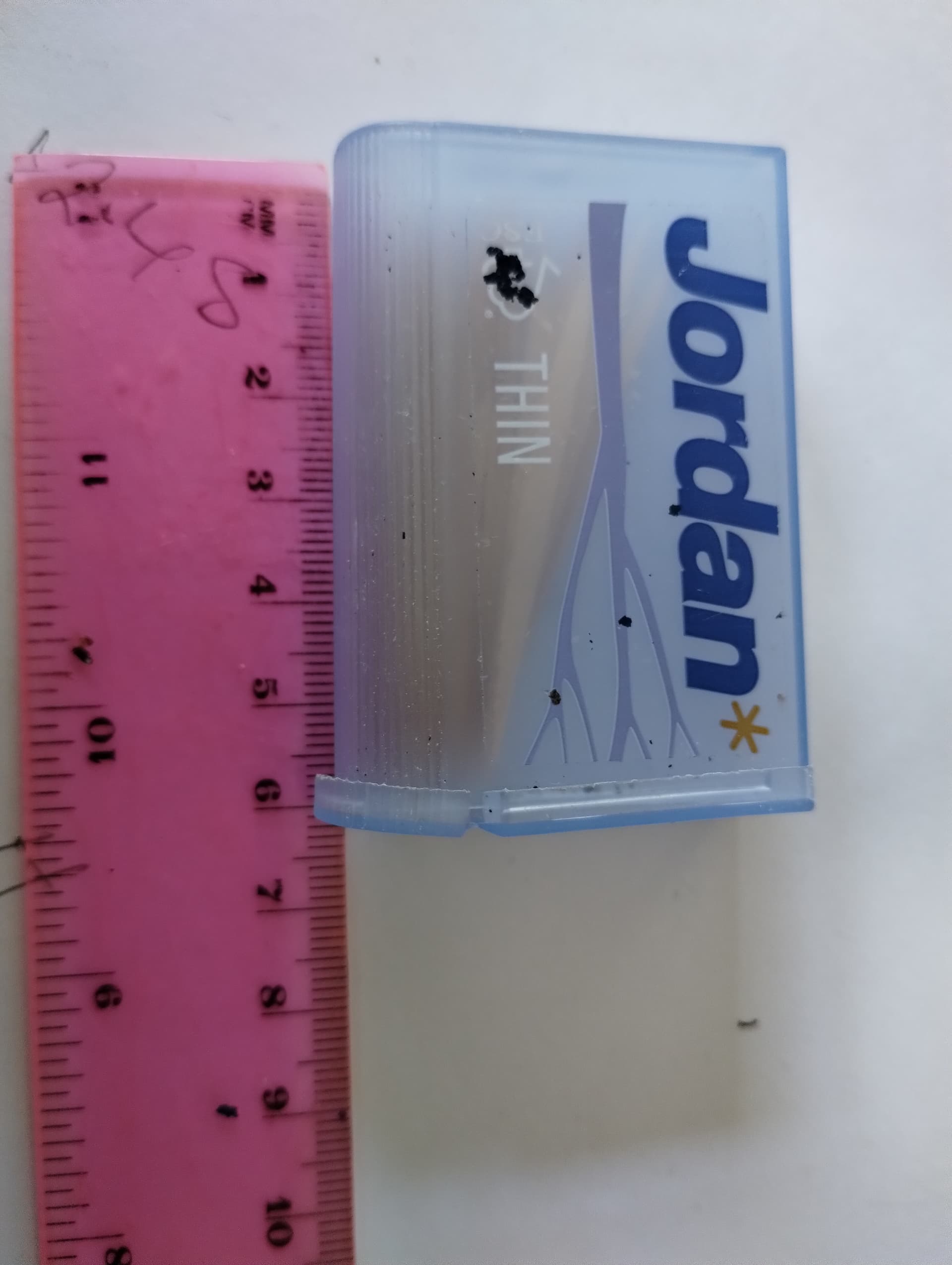
The electronics are not waterproof is there a way to protect the electronic from splashing water? I have a small plastic box containing toothpicks I can modify to enclose only the electronic in. Attached image that may keep the water out.?
-
The sample code is in C I would like to use micro python so I have with the help of Gemini Ai converted it to micro python code for Pico
import time


# Grove - Water Level Sensor addresses
ATTINY1_HIGH_ADDR = 0x78
ATTINY2_LOW_ADDR = 0x77


# I2C configuration
i2c = I2C(scl=Pin(22), sda=Pin(21))  # Adjust pins as needed


# Threshold for water detection (adjust as necessary)
THRESHOLD = 100


def read_sensor_data(address):
    """Reads data from the specified sensor address."""
    try:
        # Read 12 bytes from the high address sensor
        if address == ATTINY1_HIGH_ADDR:
            data = i2c.readfrom_mem(address, 0x01, 12)
        # Read 8 bytes from the low address sensor
        elif address == ATTINY2_LOW_ADDR:
            data = i2c.readfrom_mem(address, 0x01, 8)
        else:
            return None
        return data
    except OSError:
        print(f"Error reading from sensor at address: {hex(address)}")
        return None


def calculate_water_level():
    """Calculates the water level based on sensor readings."""
    touch_count = 0


    high_data = read_sensor_data(ATTINY1_HIGH_ADDR)
    low_data = read_sensor_data(ATTINY2_LOW_ADDR)


    if high_data is None or low_data is None:
        return None


    for value in high_data:
        if value > THRESHOLD:
            touch_count += 1


    for value in low_data:
        if value > THRESHOLD:
            touch_count += 1


    # Calculate percentage (adjust range as needed)
    water_level = (touch_count / 20) * 100  # 20 total sensor points


    return water_level


while True:
    try:
        water_level = calculate_water_level()
        if water_level is not None:
            print(f"Water Level: {water_level:.2f}%")
        time.sleep(1)  # Read every second
    except Exception as e:
        print(f"An error occurred: {e}")
        time.sleep(5)  # Wait before retrying


—-------------------------------------------------------------------------------------------------------
Explanation:
1. Import necessary libraries:

   * machine: Provides access to hardware peripherals like I2C.
   * time: For introducing delays.
   2. Define sensor addresses:

      * ATTINY1_HIGH_ADDR and ATTINY2_LOW_ADDR: Store the I2C addresses of the two sensors.
      3. Configure I2C:

         * i2c = I2C(scl=Pin(22), sda=Pin(21)): Initializes the I2C object with the appropriate pins. Adjust these pin numbers based on your Pico's wiring.
         4. read_sensor_data(address) function:

            * Reads data from the specified sensor address.
            * Handles potential OSError during I2C communication.
            5. calculate_water_level() function:

               * Reads data from both sensors.
               * Counts the number of sensor points exceeding the THRESHOLD.
               * Calculates the water level percentage based on the count.
               * Adjust the calculation based on the number of sensor points and desired percentage range.
               6. Main loop:

                  * Continuously reads and calculates the water level.
                  * Prints the water level with two decimal places.
                  * Includes basic error handling to catch unexpected exceptions.
To use this code:
                  1. Connect the Grove - Water Level Sensor to your Pico using I2C.
                  2. Adjust the scl and sda pins in the i2c initialization to match your wiring.
                  3. Adjust the THRESHOLD value based on your sensor readings and desired sensitivity.
                  4. Adjust the water level calculation in the calculate_water_level() function if needed.
                  5. Upload the code to your Pico using Thonny or another suitable tool.
This code provides a basic framework for reading data from the Grove - Water Level Sensor on the Raspberry Pi Pico. You can further enhance it by adding features like:
                  * More robust error handling and recovery mechanisms.
                  * Data logging to a file or sending data to a remote server.
                  * Implementing alarms or notifications based on water level thresholds.
                  * Using a graphical display to visualize the water level.
                  * Calibrating the sensor for more accurate readings.
Remember to consult the Grove - Water Level Sensor documentation and the Raspberry Pi Pico documentation for more detailed information.
Grove - Water Level Sensor (10cm) for Arduino


—-----------------------------------------------------------------------------------------------------------
Update for calibration


from machine import I2C, Pin
import time


# Grove - Water Level Sensor addresses
ATTINY1_HIGH_ADDR = 0x78
ATTINY2_LOW_ADDR = 0x77


# I2C configuration
i2c = I2C(scl=Pin(22), sda=Pin(21))  # Adjust pins as needed


# Calibration variables
MIN_SENSOR_COUNT = 0  # Sensor count at empty tank
MAX_SENSOR_COUNT = 20  # Sensor count at full tank


def read_sensor_data(address):
    """Reads data from the specified sensor address."""
    try:
        # Read 12 bytes from the high address sensor
        if address == ATTINY1_HIGH_ADDR:
            data = i2c.readfrom_mem(address, 0x01, 12)
        # Read 8 bytes from the low address sensor
        elif address == ATTINY2_LOW_ADDR:
            data = i2c.readfrom_mem(address, 0x01, 8)
        else:
            return None
        return data
    except OSError:
        print(f"Error reading from sensor at address: {hex(address)}")
        return None


def calculate_water_level():
    """Calculates the water level based on sensor readings."""
    touch_count = 0


    high_data = read_sensor_data(ATTINY1_HIGH_ADDR)
    low_data = read_sensor_data(ATTINY2_LOW_ADDR)


    if high_data is None or low_data is None:
        return None


    for value in high_data:
        if value > 100:  # Adjust threshold as needed
            touch_count += 1


    for value in low_data:
        if value > 100:  # Adjust threshold as needed
            touch_count += 1


    # Calculate water level using calibration
    water_level = ((touch_count - MIN_SENSOR_COUNT) /
                   (MAX_SENSOR_COUNT - MIN_SENSOR_COUNT)) * 100


    return water_level


# Calibration procedure
def calibrate_sensors():
    global MIN_SENSOR_COUNT, MAX_SENSOR_COUNT


    print("Place the sensor in an empty tank.")
    input("Press Enter when ready...")
    MIN_SENSOR_COUNT = _get_sensor_count()


    print("Place the sensor in a full tank.")
    input("Press Enter when ready...")
    MAX_SENSOR_COUNT = _get_sensor_count()


    print(f"Calibration complete:\n"
          f"MIN_SENSOR_COUNT: {MIN_SENSOR_COUNT}\n"
          f"MAX_SENSOR_COUNT: {MAX_SENSOR_COUNT}")


def _get_sensor_count():
    """Helper function to get the current sensor count."""
    count = 0
    for _ in range(10):  # Average readings over 10 samples
        count += calculate_water_level()
        time.sleep(0.1)
    return int(count / 10)


# Run calibration once
calibrate_sensors()


while True:
    try:
        water_level = calculate_water_level()
        if water_level is not None:
            print(f"Water Level: {water_level:.2f}%")
        time.sleep(1)  # Read every second
    except Exception as e:
        print(f"An error occurred: {e}")
        time.sleep(5)  # Wait before retrying


—-----------------------------------------------------------------------------------------------------
Key Improvements:
                  * Calibration:
                  * The code now includes a calibrate_sensors() function to determine MIN_SENSOR_COUNT and MAX_SENSOR_COUNT.
                  * During calibration, the user is prompted to place the sensor in an empty tank and then in a full tank.
                  * The _get_sensor_count() helper function averages multiple readings for more accurate calibration values.
                  * Water Level Calculation:
                  * The calculate_water_level() function uses the calibrated MIN_SENSOR_COUNT and MAX_SENSOR_COUNT to calculate the water level percentage.
                  * Clarity:
                  * Comments and variable names are improved for better readability.
To use this code:
                  1. Connect the Grove - Water Level Sensor to your Pico using I2C.
                  2. Adjust the scl and sda pins in the i2c initialization to match your wiring.
                  3. Run the code. The program will guide you through the calibration process.
                  4. After calibration, the code will continuously monitor and display the water level.
This refined code provides a more accurate and robust solution for water level measurement by incorporating calibration into the process.
- Taking this information into account do you have any input to improve the success of the project?
Big Thank you if you have got this far and thank you if you give me some feedback.
Peter