This is a placeholder topic for “PiicoDev Magnetometer QMC6310” comments.
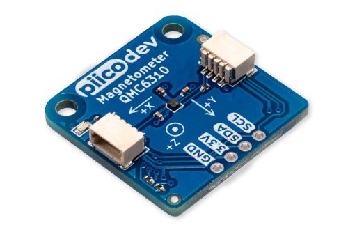
Measures invisible magnetic fields - use as a compass or to detect nearby magnets.
Read moreThis is a placeholder topic for “PiicoDev Magnetometer QMC6310” comments.
Measures invisible magnetic fields - use as a compass or to detect nearby magnets.
Read moreI’d like to use this module in an arduino-based project. Would this be possible - would I need to look at the micropython libraries to figure out the I2C interface for this device? I’d like to calibrate and then get a usable compass heading.
Hey Colin,
Getting a compass heading would be an awesome use of this board, it definitely has the capability to do so.
The issue you are going to run into is using it with an Arduino project, as PiicoDev products aren’t currently supported on Arduino. I am sure you can get the compass set up done using MicroPython, otherwise you may have to find arduino libraries for the chip used on the magnetometer and tweak it to use it for an Arduino based project.
Cheers,
Blayden
Hey Core folk!
Been trying for > 2 hours to calibrate this on a raspberry pi4 - following Michael’s awesome guide - but no matter what I try, or how many times I try, or how slow I go… I can’t get it to calibrate a full 360 rotation where it’s not mangled for at least 90degs of it.
I’m also having to rotate it 3 or more times, instead of the single rotation Michael was able to do.
I’m laying it flat on a table and rotating it like Michael did… only difference is I don’t have long STEMMA cables, so maybe it’s too close to the rPI - but There’s not much I can do about that.
Any ideas?
Cheers,
Seon
Hi Seon,
Sorry to hear that sensor isn’t calibrating as nicely for you.
Can you post a quick photo of your setup? Just so we can give everything a look over and make sure everything looks normal with the physical setup of the device.
Were you just using the PiicoDev example code compass.py to start with? Or have you pulled that calibration routine from our code and are integrating it into your own code?
The cables shouldn’t matter too much provided the distance is short enough that the I2C messages can get through ok. Were there any other devices currently on the same I2C bus connected?
The comment re short cables is that it’s hard to rotate 360 or more as it twists and gets shorter - and it’s close to the rPI.
Cheers ![]() Seon
Seon
Hi Seon,
Ah that would be a challenging cable to calibrate with. Michael doesn’t make a particular mention of this in his guide but it is best to try and rotate the sensor without it translating as much as possible.
Ideally you want the sensor in the centre of the magnetometer to stay in the same place and only have a rotation on the spot.
One other aspect that might be worth consdering is the environment itself you are in. You mentioned that the calibration is a bit mangled for a 90 degree segment. Is it always the same 90 degree orientation that has the issue, or does it change each calibration?
I.E does it always play up when facing east but otherwise works correctly?
It may also be worth moving your setup if it is reasonably portable and repeating the test, just to see if the issue is consistent if your project moves to another location. If it works normally when moved you may have inadvertently detected a source of magnetic interference while trying to calibrate.
Let me know how you go with those variations to the calibration routine and we’ll look at replicating your setup here with the same length cable, just to see if we get the same result.
Hey Trent,
It’s a different area every time… clearly based on my rotation ability… not from interference I don’t think.
Is it possible to share a calibration that you have that works? I don’t care where North is (real or magnetic) I just want to have a 360deg rotation starting for anywhere, so maybe loading a better quality calibration will be fine for my needs.
At worst, I can compare the 2 to get a better idea of what’s mangled in mine.
Thanks ![]() Seon
Seon
Hi Seon,
Our forum doesn’t like the .cal extension as an attachment because it’s an unknown file type.
I’ve included the contents of my calibration.cal file below so you can see how it compares to your file.
x_min:
-1058.2146018266956
x_max:
1038.4543284868953
y_min:
-1081.0529140387994
y_max:
1050.9663108317977
z_min
100.70854006034278
z_max:
263.22302051782253
x_offset:
-9.88013666990014
y_offset:
-15.043301603500822
z_offset:
181.96578028908266
FYI It took me 2 full rotations to get a calibration even using the 500mm PiicoDev cable, so perhaps Michael got lucky during the video when he got his in just one rotation.
I did try the 100mm cable and not having enough space to rotate the magentometer around a fixed point definitely makes it take longer to calibrate, though I didn’t observe any changes in the quality of the output it gave once it had calibrated successfully. I certainly haven’t seen a 90 degree window with mangled results with the unit I’ve tested
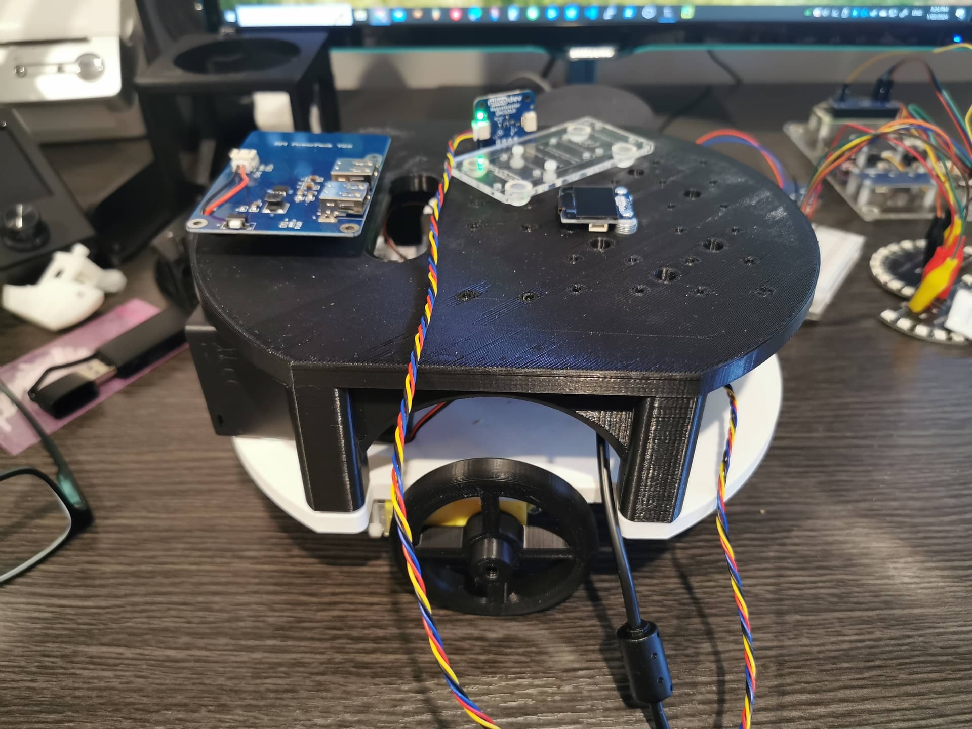
I’m having a weird issue as well with the calibration. I bought the Magnetometer a few months ago, but other than the quick play I had (along with the other Piicodev sensors I received that day), I haven’t used it until today. I’m using it as a crude guidance system for a 3d printed robot I’m making i.e. take current heading ± 90, turn to that heading, and start moving and so on (…and add more functionality). I’ve followed my nose and done everything outlined above, but the calibration is weird. I can leave the sensor stationary, and the calibration bar moves by itself, or I turn it clockwise, and I get no progress at all. Other time when it completed the calibration, ~90 degrees on the screen, would equal ~200 degrees on turning the sensor. I did look at the calibration file and it was sad reading to say the least. I’ll do a fresh install of everything on the device to make sure there’s not unforeseen conflicts between versions.
Hi Laurence,
What kind of environment do you have it setup in? If its close to your motors or any wires coming from the battery there will be some interference.
Keen to see some pics of the robot!
Laurence.
Edit: and even now it can “calibrate” on it’s own, slowly but surely, 1 then to 3, 1 to 5, then 1 to 10 asterixis ![]()
Hi @Laurence257160 - I was involved with the design and educational material for this product so I hope I can help shed some light on what’s going on.
The calibration process is what is known as “hard iron” calibration. It’s to remove any (constant) offsets introduced by eg. magnetic or ferrous parts near the magnetometer.
For this process to work with a robot, the magnetometer needs to be mounted to the robot and the whole robot rotated during calibration.
The point here is to remove the (constant) influence of the robot parts. I’m afraid magnetic fields generated by the motor activity are impossible to calibrate out…
The calibration procedure looks for new minimum and maximum readings, and resets the progress bar every time one is found. The assumption here is that the magnetometer is always being steadily rotated during the process. If the magnetometer is not being steadily rotated the calibration is invalid.
After a while of not being rotated, new minimum and maximum values will not be found (aside from whatever noise is in the reading) and the calibration will assume to be complete even though it is invalid.
Build the functionality up in steps to make sure each layer of complexity is well understood before moving to the next step.
Once you’re confident with the calibration process,
Now that you have a working compass mounted to the chassis, you can
I hope this helps clear a few things up. please let us know how you go.
This looks like an awesome little platform ![]() I’m excited to see it in action
I’m excited to see it in action
Happy Making!
Thank you for the deeper explanation of the calibration process.
We built this house 4 years ago and thinking back to the construction there is iron reinforcing bars through out the entire concrete pad, and power ducted through the ceiling (NZ building standards) . Will definitely try elsewhere (like the garden!!). I unfortunately nuked the code last night thinking I had a back up, so I may go for timing for turning if the magnetometer doesn’t work out. I did have a simple stop/go routine using the Ultrasonic sensor. Will be fairly quick to recode. In future projects I may use stepper motors, but I’m learning a lot from a basic project.
The robot base came from a decision to spend NZD$400 on a Creality Ender 3 v3 and print as many robot chassis as needed (including wheels) instead of NZD$100 on a chassis. The top is meant to be Piicodev friendly so I can mount other sensors and screens on top. Again it’s work in progress, and further iterations will evolve.
Regards, Laurence.
This is great! It warms my heart ![]() to see makers building cool stuff around PiicoDev, and even accommodating it in their design process
to see makers building cool stuff around PiicoDev, and even accommodating it in their design process ![]() Love your work! Keep us updated
Love your work! Keep us updated ![]()
Hi guys, would the qmc6310 magnetometer be able to detect a fairly strong magnet passing by at about 1-2m range?
Hi @Stuart162817,
Unfortunately, this is a bit of a difficult one to answer without knowing the strength of your magnet.
The datasheet for the QMC6310 says it has a sensitivity of ±30 gauss and the magnetic field of the earth is around 0.5 gauss if that gives you an idea of what it can pick up.
Hope this helps!
Hi Stuart,
In short no, the magnetic field strength falls off very quickly over increasing distances.
What is it you are trying to achieve? There might be a better sensor suited for the job
And you can get our latest projects and tips straight away by following us on:
![]()
![]()
![]()
![]()