Agreed, very strange. For the time being I am moving forward with what we have but will loop back to dig into it further when I get some more time, as I’d like to understand if I’ve done something wrong or if I am just expecting the device to do something it isn’t meant to do.
I had sent this information (prior to finding the RS232 hack) to waveshare support as well, but based on their response they think I am using a MODBus device, so I will continue to explore it with them as time permits as well.
Based on your correct packet and your posted data for the bad packet, im fairly sure the data is inverted. as it hits the serial decoder as such its not just a simple case of inverting the data in putty as some bits will be mis alligned etc.
But with some number hacking, I did get “!AI” out of the wrong data as I would expect to see it.
As such I would be looking at the wire connection between this device and your source device as I suspect the +/- on the TX->RX is backwards.
This also matches my post above with which “wire” you connected to the RS232 RX pin, that also seemed to be the wrong one, but gave you correct data, so it seems to line up for me without actually having the devices in front of me with my test gear.
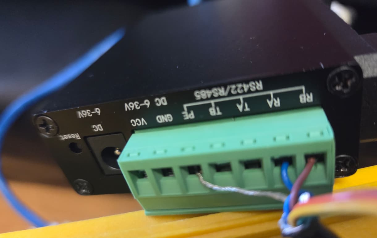
You were spot on Michael, it was inverted, I switched the Tx- and Tx+ wires around and it now works.
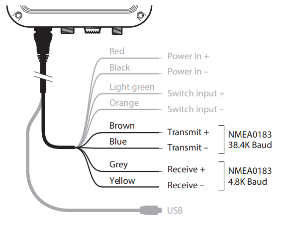
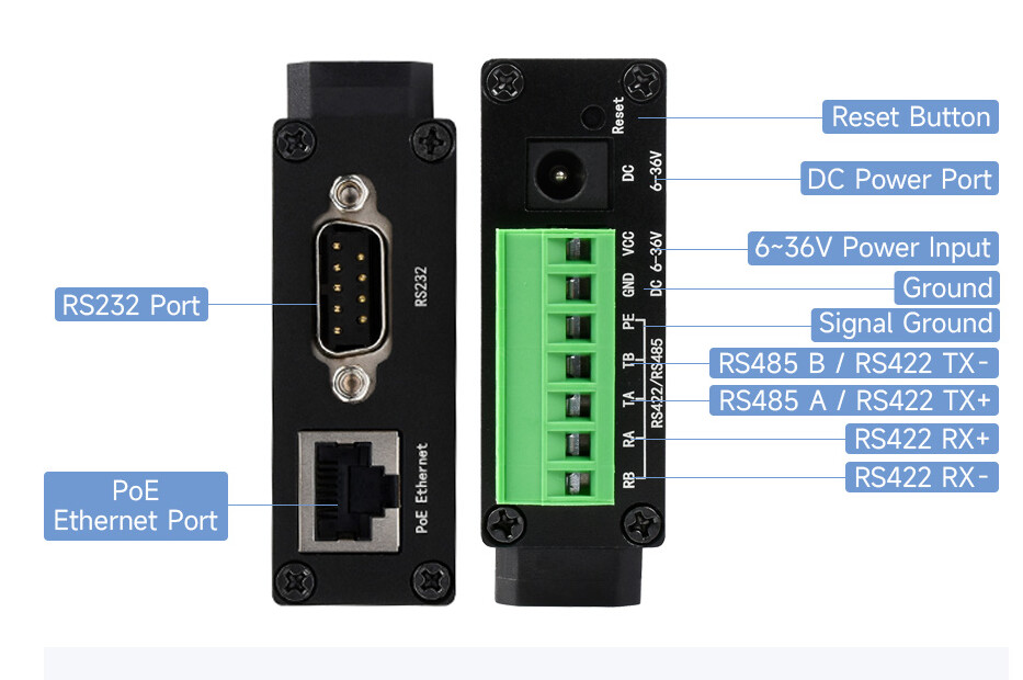
This is the opposite of what I thought it was supposed to be, which your RS422 diagram points out it should be TX- to RX- and TX+ to RX+, however the current working wiring I have is TX+ (Brown on AIST120) to RX- (RB on Serial Server) and TX- (Blue on AIST120) to RX+ (RA on Serial Server) per the following diagrams snapped from the manual. We know the AIST120 cabling is correctly labelled as this correctly worked when wired AIST120 TX RS422 to Serial Server RX RS232, so that would suggest the labelling on the Serial Server RS422 interface is incorrect.
I want to use two of these to tunnel RS485 over an Ethernet network. Is that straightforward with the Waveshare firmware? Can I just point the units directly at each other to connect two RS485 devices over an Ethernet network? I don’t need an MQTT bus or anything in the middle? Do you use different IP ports for input/output or bidirectional on the one port? And UDP is used?
While I have not actually used these as such, normally you would set one up as a server (and any inbound port redirects etc on your firewall if needed).
Then the other as a client, that connects to the server.
I would test on a local lan first just to keep things simple.
Not quite sure how you are going to do that. RS485 is a two wire (1 pair) balanced line not unlike balanced audio. The receiving end senses the voltage DIFFERENCE between the 2 wires. Nothing is referenced to ground. The CMRR of the modern OpAmp is so good that very long cable runs are possible with this system with common mode interference being almost completely rejected.
With this in mind I don’t quite see how you are going to achieve this. The system is designed to operate over physical wires.
Cheers Bob
Hence the module. It will take the RS485 (or what ever it supports) “read” its state and send that to the remote unit (in this case over TCP/UDP), the remote unit then simply dumps the state of the original wires to the local wires.
that said, the question I want to ask, but try not to, is more about the “why”. If its all local, can you just run a cable an not need any converters. But I think now a-days people have access to ethernet cabling, can use that and not run any new wires. And in bigger buildings the device could be over 500m away and optic fibres for data are already in and running, so to run it over some IP protocol to a central controller/monitor just makes sense. I look at the security systems and door tap/swipe controllers. In the paste the would all run over a few wires back to the main security rack, but now, all the new readers run over the data network. Same for video cameras… everything now “must” run on the data network.
Hey there, @Threaded, and welcome to the forum. Glad to have you here.
When you say ‘Ethernet Network’, what exactly do you mean? If you’re using a Switch with a Router or a Layer 3 Switch, then as long as each module is connected to a machine with a valid IP and both are properly configured, that should be fine. All the serial data would just be encapsulated within the IP Packet (technically an L4 datagram but that word sounds awful) and decapsulated at the other serial port.
If, however, you just
In that case, as an intellectual exercise, it’s eminently doable. If you are needing this for a professional project, I must agree with @Michael99645 unless you absolutely need two devices to communicate via serial.
Edit: Upon rereading, I just want to confirm that you don’t mean having two serial devices connected like the below:
Because that probably won’t work unless the Serial devices can handle Layer 2 and Layer 3 routing and you would need to be sure you have a crossover cable.
I’d have to trench new cables between buildings to have dedicated RS485 lines. Whereas we have Ethernet bandwidth in bulk. Plus each current cable provides at least 10,000,000,000 baud, so running a separate cable bus everywhere just for 115,000 baud seems, um inefficient
@Jane the path would be as below and to the Serial Devices A & B it would just be an RS485 conversation between them. I think it should work fine, but I want to check the Waveshare firmware was capable.
Serial Device A
|
PoE RS485<->Ethernet Module
|
Ethernet Switch
|
TCP/IP network
|
Ethernet Switch
|
PoE RS485 ↔ Ethernet Module
|
Serial Device B
Thanks @Robert93820 the products we are discussing convert messages from RS485 serial bus to/from packets on a TCP/IP network. E.g. you can feed all the messages to/from a bunch of RS485 devices to/from MQTT bus topics. Here I just want to convert RS485 messages to TCP/IP packets then convert them straight back RS485 messages somewhere else - and vice versa.
Yeah, maybe
Im mostly for optimizing the use of existing infrastructure as opposed to extra cost for little to no gain.
Some little things to keep an eye one is how well some middle-ware device/system can do the job.
10 Gig Links != 10 Gig perfect end to end. e.g. IP Based (even ethernet) is really a best effort based on device capabilities, configs (qos) and other traffic on the same network. The 10 Gig simply means that if both ends support it, and its your time to send/receive data, then that data will move at 10 Gbps.
So one key challenge when we convert from what “is” a point to point link with “perfect” timings to IP based traffic is we are adding in random delays. The effect of these delays will range from no-affect to random errors, to it just does not work.
So as we move from hard-wired to Ethernet, we need to ensure it can be stable and reliable. With serial comms (based on the tools I have seen and used) happens in a store and forward manner. i.e. each bit does NOT arrive at the other end as its sent, rather, a packet is sent over the IP network; thus, in theory removing any network delay and protocol timing issues.
e.g.
SRC RSxxx device want's to send "hello world"
It clocks out the binary for h...e....l...l...o ..... l...d   and each byte is encode as per the line level standard.
The RXxxx to IP then receives that as a hardwired RSxxx end point.. and stores in a buffer.
"hello world"   that buffer is then sent to the remote unit over whatever IP protocol that was setup,  The remote unit then clocks that out onto the RSxxx wire as per the standard.
This works very well for line-based protocols. When their is no clean line-based protocols, then there will be timeout settings “send when no data seen for X amount of time” sort of approach.
OK so now that we accept that there is some middle-device doing things that can break up the comms, we simply need to setup and test and debug.
each of these devices, as a point to point, really should just pass the traffic in such a away that if :
a) We look at the data at the RS485 wires we should see the same data each end, just offset by some amount of time (due to the to ip and back)
b) We look at the data at the IP level; we would expect to see some form of a structed packet
(as an example)
So if things are not working, data capture at, “RS485 input/output” and network level should help ID the issue.
My 2 POE Units Arrived today, So I run some quick tests.
My Setup is as follows
USB-RS485 into my PC connected to putty. RS485 connected to Unit 1
USB-RS485 into my PC connected to putty. RS485 connected to Unit 2
I setup some fixed DHCP Leases for both units mac addresses.
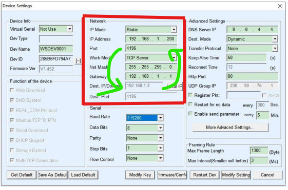
I then used VirCom - Device Management to discover the devices on my LAN. They came with default IP address outside my LAN IP subnet, but VirComm found both units, So I grabbed the mac addresses for each (Dev ID) and set IP Mode to DHCP.
On one unit I ensured it was setup as TCP Server (nothing else changed)
On the 2nd unit I ensured it was a TCP Client (work mode), and gave it the IP address of the first unit (server), left the ports and baud etc all as defaults.
At this point this gave me
Putty → USB RS485 → Unit 1 (Server) → Local LAN → Unit 2 (client) → USB RS485 → Putty
So when I typed into one putty window, the key appeared on other other (and visa a versa). This proved that all the comms were working in a stand alone RS485 over TCP/IP.
Next step I connected the RS485 to my logic analyzer so I could check the latency.
In this setup, From start of RS485 data on one unit, to the start of RS485 data on the 2nd Unit (i.e. covers the end to end latency), there is a 3ms (average) delay.
So the conversion and IP transmission is adding about 3ms latency for a byte transmission to reception.
this may or may not be an issue in a particular setup, but timeouts and end to end software MAY need to be checked and tuned
So in conclusion, Yes they can be a stand alone RS485 RS485 over TCP/IP, and yes there is latency introduced in doing so.
Happy to check/test anything else if needed by others.
On a side note. With this device, in “default” mode you can connect directly from software.
e.g. Put the device into Server Mode, then from your software, make a TCP connection to the device. Any data sent over the TCP connection is then clocked out on the serial side and any data from the serial side is just sent as the data payload for the network connection (also works when the device is in client mode with your software being a “server”.
Note: RealCom and other modes have a header in the playload that seemed to be A few bytes long; but realcom is not needed for a basic connection.
The device discover is a UDP broadcast, and I have mapped out most of the discovery packet and config fields.
As such, if you were looking to make your own connections via some micro controller then you dont need/cant use the waveshare drivers/software, then this should be very possible.
Note: This is only useful if you are writing your own applications and wanting to talk to some serial device over the network. If you are trying to just use the network as an extension for the serial and are using existing software, then you will still need the virtual serial port for your legacy application to connect to.