Raspi BirdBox Advice

Hey there gurus.

I’m hoping for some advice on a little project I’m embarking on. My 6 year old son has recently become fascinated with the Rainbow Lorikeets that regularly visit our back verandah, and subsequently commissioned his pop (who’s a little more handy than his dad) to build him a nice Lorikeet bird box.

To make it a bit more fun, I was hoping to install a camera and stream live video, so we can keep an eye on who’s moved in and what they might be getting up to.

I’m pretty familiar with developing solutions with Raspberry Pi’s so I figured I’d go with a Raspi Zero 2 W, NoIR Camera and the official case which can house the Pi and the camera.

What I’m a bit unsure of is:

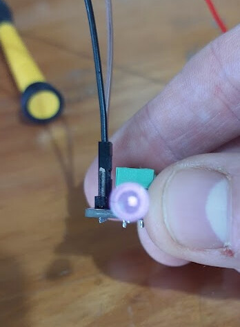
  1. Do I need some additional light source for the camera? - something like this perhaps Super-bright 5mm IR LED - 940nm | Buy in Australia | ADA387 | Adafruit | Core Electronics which could be triggered by the GPIO pins

  2. What is my best option to power something like this? Ideally I’d like to run this constantly off solar power, so I don’t need to run power to it (as it will be installed outdoors, up a tree). I assume I’ll need a small solar panel, battery and a controller of some sort to make this work, but any help with exactly what those parts would be (based on power requirements etc), would be greatly appreciated.

  3. What’s the best software / script / library out there to stream the live video to our local network. I (preferably) just want to be able to view the activity from a web browser on a phone, tablet or PC. If the camera setup could be triggered by someone accessing the live feed, that would be ideal, especially from a power saving perspective.

Thanks in advance.

2 Likes

Hey @Shane53869,

Welcome back to the forum!

Sounds like a brilliant project, your son is going to love it. Great idea combining some wildlife watching with a bit of fun tech.

Camera and Night Vision
The NoIR camera is great for seeing in low light or at night, but you’ll need a small infrared light to help it “see” when it’s dark. This one works well:

You can start with the IR light always on at night, which is easier than wiring it to turn on automatically. Later on, if you want to get fancy, you can set it up to turn on only when someone accesses the video feed or when motion is detected, to save power.


Powering It with Solar
Since you want to run this outdoors and off the grid, using solar power is a good choice and saves having to run cables up your tree. Instead of building a custom setup, you can use Core Electronics’ PiJuice Zero system, which is designed to make solar power for Raspberry Pi easy and plug-and-play:

This setup is basically plug-and-play, no complicated wiring needed. The solar panel charges the battery, and PiJuice safely powers your Pi Zero 2 W while managing the battery. It even has software that can turn your Pi off at night or when the battery is low to save power.

For a step-by-step guide, Core Electronics has a helpful tutorial here:


Streaming the Video
For streaming the live video over your home Wi-Fi so you can watch on a phone or computer, MJPG-streamer is simple and works well. Another option is motionEyeOS, which has extra features like motion detection.

Both let you view the live feed in a web browser.

If you want to get more advanced later, you can set up the camera and IR light to turn on only when someone is watching to save power, but starting with continuous operation will be much easier.


Other Tips

  • Make sure your case protects the Pi and battery from weather but has some airflow so it doesn’t overheat.
  • Test everything indoors before mounting in the bird box.
  • If Wi-Fi is weak where the box will go, a Wi-Fi extender might help.

Looking forward to hearing how it all goes. It’s a fun project and a great way to enjoy nature and technology together.

1 Like

Wow Ryan, thanks so much for getting back to me so quickly.

And with such comprehensive answers to all my questions there mate!!!

2 Likes

Hey @Shane53869,

No trouble at all, that’s exactly what we’re here for! Excited to see this project take shape, and we’d love to hear how it all turns out, so keep us posted.

1 Like

Hi Ryan,

Thanks again for all your help.

This might be something that’s a recent change but it looks like you guys have retired the PiJuice Zero. I just wanted to confirm that the recommended replacement, the Witty Pi 4 L3V7 will serve the same purpose in this scenario. If so, would you also recommend using this battery Polymer Lithium Ion Battery (LiPo) 18650 Cell (3.7V 2600mAh, Solder Tab) | Buy in Australia | CE04625 | Core Electronics listed on the product page.

Also, do you think would this be a suitable solar panel choice for this application - Solar Panel Charger - 10W | Buy in Australia | PRT-16835 | Sparkfun | Core Electronics. If not could you recommend a 6W and a 12W option as listed in your original message.

And finally (sorry if this is a dumb question), how does one wire up the IR LED if there is no access to the GPIO pins on the Pi zero, since the power management board plugs in on all of the headers.

Thanks

1 Like

Hey @Shane53869,

Thanks for the follow-up. You’re right, it looks like the PiJuice Zero was officially retired just yesterday. The Witty Pi 4 L3V7 is a good alternative if you’re looking for time-based power scheduling and safe shutdown functionality, though it doesn’t include solar charging like the PiJuice did.

To power your setup from solar, you’ll need a dedicated LiPo charge controller. This Solar LiPo Charger (3.7V) is a great option and is designed to safely charge 3.7V LiPo cells from a solar panel or USB input.

As for the battery, the 3.7V 2600mAh LiPo 18650 cell with solder tabs that you mentioned is a suitable choice. Just ensure it’s connected with a JST-PH 2-pin connector and that the connection is secure with appropriate strain relief.

The 10W solar panel you originally linked is compatible. For completeness, here are two other panels that also work well with the above charge controller:

If the GPIO pins are obstructed by the Witty Pi or another HAT, there are a few ways you can still connect an IR LED:

Use a stacking header
This lets you physically stack the Witty Pi while still exposing the GPIO pins underneath.

Connect directly to the Pi’s 5V and GND rails
If you don’t need to control the IR LED, you can power it directly from the 5V pin with a suitable current-limiting resistor. This keeps it on whenever the Pi is powered.

Hi all,

Thanks so much for your help and advice so far. I’ve finally managed to find some time to purchase and put together my little bird box project.

It still pretty early days, but I put the pi together with the camera in a Pi Hut Camera Case (The Pi Hut Pi Zero Camera Case | Buy in Australia | CE07178 | Core Electronics), and managed to get a stream up and running.

I’ve also managed to integrate one of these LEDs into the case. I’m just not completely sure what size resister I need to run this off one of the Pi’s GPIO pins. My basic electronic knowledge tells me that when calculated a 17 ohm resister is what I need (Forward voltage of the LED is about 1.6V and the Continuous forward current is listed as 100ma on the spec sheet).

Google says that 100 mA is quite high for a Raspberry Pi GPIO pin. Most GPIOs are rated for a maximum of 16 mA, and exceeding that can damage the Pi.

Just wondering what I should do here, to ensure that I don’t break anything but still get sufficient brightness through the LED to see in the (relative) dark.

Thanks again.

1 Like

100mA is far too high for a Pi GPIO port. A typical small LED is about 15mA, but generally you wouldn’t want to drive a Pi GPIO port at more than about 10mA. And don’t forget that there is a maximum overall figure, so you have to consider what else is connected to the Pi.

There are simple single-transistor circuits that you could assemble for driving a LED at that current, but perhaps the easiest approach is a dedicated LED constant current controller:
Adafruit TPS61169 Constant Current Boost Converter for LEDs | Buy in Australia | ADA6354 | Core Electronics

That module has the advantage that it would be usable with a range of different LED configurations so that you can experiment to get the best effect.

1 Like

Thanks Jeff, for sharing your knowledge and advice. Very much appreciated. I realise now that I didn’t provide a link to the IR LED I’m looking to use - Super-bright 5mm IR LED - 940nm | Buy in Australia | ADA387 | Adafruit | Core Electronics

Given that this will be the only LED attached to the Pi for this project, I suppose I could try running it at 10mA to see if would suffice for the application. It’s worth noting too, that it wouldn’t be powered on all the time. My intention is to start the camera stream and illuminate the LED only when a client connects to stream.

It does however, sound like the little Adafruit current booster you recommended is probably the go.

There is also the possibility that I’m not interpreting the spec sheet correctly for the iR LED which is here: Microsoft Word - IR333-A.doc

Thanks again.

2 Likes

Interpreting that data sheet is not easy. The Absolute Maximum for continuous operation is 100mA. But the absolute maximum figure for a device is usually well above the recommended operating conditions. The table has a footnote “Pulse Width≦100μs and Duty≦1%” but that appears to apply to the 1A Peak-Forward Current rating (although the asterisk is missing), so it’s not clear what typical usage at 100mA might be. The electrical parameters are provided at 20mA (presumably continuous), 100mA at a Pulse Width≦100μs with duty cycle ≦1%, and 1A at Pulse Width≦100μs with duty cycle ≦1%. Other figures are quoted at 20mA. But the operating conditions chosen for these references are often arbitrary and may not reflect the available operating envelope. The description of suitable applications and the very narrow beam angle suggest that it is primarily intended for IR detection, not IR illumination. That doesn’t mean it is not suitable for IR photography, but it does make interpreting the data sheet difficult.

The advantage of the adjustable boost converter is that you can try different settings. How hot the device gets in the actual operating conditions is a good guide to how long it is going to last.

2 Likes

Thanks again Jeff for the comprehensive response. Very informative.

I’ve gone ahead and purchased little Adafruit current booster you recommended previously, and this might sound like a dumb question but does this device provide the resistance in the circuit based on the required current you dial up on it, or do I still need to wire up a resister?

Also, I’m guessing the wiring is simple - ie. GPIO pin and GND on the Pi → + / - Terminals of the current booster (3-5Vin), then + / - (CC Out) out to the matching sides of the LED?

Thanks in advance.

Yes. The resistor is a substitute for a constant current source that works OK for simple cases but can be difficult to use with more complex configurations. The constant current source does what a resistor does but with much better control. It also gives you the ability to quickly test different configurations just by flicking the switches.

Note that the PWM input (in the header row) is described as enabling dimming for the LED, but it works just as well to simply turn it on or off - this is what you will use with the Pi. For testing without the Pi, if the LED won’t light you may need to connect this pin to either the Vin+ or Gnd pin. The input side will be a 3~5V source (+) and ground (-). This source could be the Pi 3V pin, or the 5V supply you are using for the Pi. Ground is the common ground used for the Pi and the supply. Then the LED is wired to the output terminals + and -. There is no need to connect the output - to ground.

The switch configuration is simple. With all switches off it will deliver 25mA. Each of the switches can then be turned on individually or in combination to add the indicated additional current, so with those combinations you can set it to any current between 25mA and 400mA in 25mA steps.

When connected to the PI, with the PWM header pin wired to a Pi GPIO port, you can set the GPIO output HIGH or LOW (I am not sure which is ON and which is OFF) or you could get fancy and drive it with PWM to get full control over the brightness.

2 Likes

Thanks again Jeff.

So I took your advice and ordered myself one of the adjustable boost convertors you recommended but I’m struggling to get it all to work.

I’ve connected it up as you advised after having soldered headers to the boost convertor. Then I’ve connected it as follows:

  • 3v pin on the pi to Vin on the convertor
  • Ground pin on the pi to the ground pin on the convertor
  • GPIO pin on the Pi to the PWN pin on the convertor
  • Positive pin on the LED to the L+ pin on the convertor
  • Ground pin on the led to the LED - pin on the convertor

I’ve then got a simple python script to turn the LED on, which I’ve proved works by constructing a simple circuit with a standard LED.

It doesn’t however seem to work with the IR LED, and I’ve read that I won’t be able to see it, but might be able to capture it illuminated with a camera. So far I can’t detect that its turning on.

I’m also using a utility called mediamtx to do the streaming and it allows for code to run when a client connects to the stream. I’ve configured my ‘led on’ script to run on connect and even when the camera is operating in darkness, I cannot see that the LED is lit, nor is anything visible on the stream.

I know this setup is quite bespoke but if you had any advice or something I could try, that’d much appreciated. Its putting a bit of a halt of this project.

Thanks again.

1 Like

If it works with an ordinary LED then it should work with the IR LED, unless it’s damaged. With the converter configured for 25mA you should measure a voltage across the LED of about 1.25V. If it’s less than about 1.2V then the LED won’t light. If you have more than one digital camera then it would be worth trying them all to see if you get a response. Don’t forget that the IR LED has quite a narrow illumination angle - if you are looking directly at it anything more than about 10 degrees off the centreline will be considerably down on brightness. To test the IR camera you should be able to see any heat source that stands out from its background - a soldering iron would be a good example.

1 Like

Hi Jeff. Once again, thanks for sharing your knowledge.

Based on your advice, I did some testing with a multi meter and what I found was pretty interesting.

When I tested the IR LED I’d initially wired up I found that the voltage across it was the same as whatever constant voltage pin I had the Vin pin connected to - 3V or 5V.

I switched out the LED (because I bought 3, just in case) and found that the voltage measured across it was 1.2V. So, I wired everything up without the PWN pin connected and again I couldn’t see that the IR LED was illuminated - until I used my wife’s phone camera, and bingo - it was obvious that it was lit.

At this point I figured we were back in business, so I wired up the PWN pin to a GPIO pin on the Pi and using a script that I’d previously used to light up a standard LED, I attempted to switch on the IR LED as per your previous advice but I simply can’t seem to make it work. I tried various settings on the boost convertor, from 25mA (all switches off) up to 100mA but nothing seems to work.

I’m simply setting the GPIO to high to turn on the LED, and low to turn it off.

Is there something that I’m missing??

1 Like

Good - the Constant Current Converter is doing its job of adjusting the voltage at the LED to whatever is required to maintain the correct current, regardless of its supply voltage.

You don’t need the MCU to test the operation of the PWM pin. The PWM input to the module is tied LOW, so by default the device is turned off. To turn it on you need to supply a voltage higher than about 1.2V to the pin. This is what the MCU should do when you set the GPIO output to HIGH. But you can do the same thing manually by simply connecting the PWM pin to 3.3V. You have mentioned that you are driving the converter at either 3.3V or 5V, so you can just connect PWM to VIn to turn it on.

If that works then the problem is with the GPIO. You can measure the voltage at the GPIO pin as you set it HIGH and LOW. You should get very close to 0V when LOW, and something above 3V when HIGH.

1 Like

Thanks again.

I feel like I’m missing something simple here so sorry for asking, but just for clarity, how do recommend that I should connect the Pi To the constant current converter so that I can switch the LED on and off??

To control the LED from the Pi you would connect a Pi GPIO pin to the Converter PWM pin, and then use code in the Pi to set GPIO port to HIGH to switch the LED on and LOW to switch the LED off.

But for testing you don’t have to have the Pi involved. To test you can simply set up the converter, a power supply and the LED.

You tested the LED with the converter and it turned on, but you also need to know that you can turn it off. There is an inconsistency at this point, but it doesn’t matter a lot. As I read the data sheet the LED connected to the converter should be off when nothing is connected to the PWM pin, and on when the PWM pin is connected to a positive voltage greater than 1.2V. If the LED is on by default then that means that I am reading the data sheet incorrectly and you would connect the PWM pin to ground to turn it off. Whatever, you should be able to turn the LED on or off by connecting the PWM pin to either the converter supply voltage or the converter ground.

When you can turn the LED on or off then you can connect the PWM pin to the GPIO. But if that’s not working you need to confirm that you code really is switching the GPIO pin between 0V and ~3V, to mimic exactly what you did when you manually moved the PWM connection between converter ground (0V) and converter supply (~3V).

1 Like

Many thanks once again Jeff. I really appreciate the assistance.

Testing the controller, whereby its simply connected to a power supply, and nothing is connected to PWM pin, the LED is lit as soon as power is connected. Connecting the PWM pin to ground, dims the LED slightly but does not turn it off.

Connecting again to the Pi, I’ve got it setup like this:

VIN → 3V pin on Pi

GND → Pi GND

PWM → GPIO18

LED+ / LED– → LED

Everything I’ve read to this point states that this is how it should be connected and that simply setting the GPIO pin to low should turn the LED off, and back on again when set to high.

At this point I’m pretty much out of ideas, beyond thinking the controller is faulty in some way.

1 Like

That’s what I would expect. The part of the data sheet that I am relying on is at P10:

6.4.1 Operation With CTRL
The enable rising edge threshold voltage is 1.2V. When the CTRL pin is held below that voltage the device is disabled and switching is inhibited. The the[sic] device’s quiescent current is reduced in this state. When input voltage is above the UVLO threshold, and the CTRL pin voltage is increased above the rising edge threshold, the device becomes active. Switching enables, and the soft-start sequence initiates

UVLO is the power supply lockout voltage of ~2.4V, so you are meeting that. CTRL is held LOW by a 300K pull down resistor. The CTRL pin rising edge threshold is ~1.2V. You are meeting those specs so it should work.

The alternative to simply switching the GPIO pin on and off it to drive it in PWM mode. The connections are exactly the same, but instead of setting it high or low you set it to a high or low duty cycle in PWM mode. So where you have

digitalWrite(18, HIGH); // Switch LED on

you would change it to

analogWrite(18, 255); // Set LED PWM to max

and where you have

digitalWrite(18, LOW); // Switch LED off

you would change it to

analogWrite(18, 1); // Set LED PWM to min

(That’s for the Arduino IDE - other languages will have equivalent code). It’s an easy change so well worth a try, although I don’t know why it should be different than what you already have.

1 Like