I’m planning on connecting a Raspberry Pi Piico 2 to the Waveshare SX1262 LoRa Data Transfer unit (WS-23596) via the CE RS232 to Serial Converter (CE04442). Based on my reading of the Serial Converter, a TTL shifter won’t be required if I power it from the 3.3V pin of the Pico, as this will result in 3.3V logic levels. Is this correct?
Can I get you to draw up how you plan everything to connect and talk to each other (at this stage block level should be ok).
Most of that gear will most likely be using UART not RS232. But if you want to connect RS232, then you may need the RS232-UART converter at the correct UART voltages. But its a bit hard to say until I can see a clear picture of what you want to do.
Cheers
1 Like
Apologies for the delay - diagram attached
Diagram1.pdf (47.2 KB)
1 Like
I should be fine to run the pico uart directly into that uart-RS232, then the RS232 to the RS232 on the Lora Unit.
One thing to keep in mind, you will need the correct cable between the RS232 ports.
I have not checked the actual Pinout to confirm, but physically, both have the “hex nuts” so you cant just plug one directly into the other.
See, image the 4 things I have draw a red line two will block it plugging in.
So you need the cable for male to female.
Maybe someone from core can confirm the pin out and what cable.

1 Like
Yes, I’d noted issue with the hex nuts. I’ve not made a decision on cabling yet. The Waveshare unit only has Tx/Rx/GND pin out connections at their end, matching the standard Serial port config. Thanks for the assist, I wasn’t sure that I was interpreting the short description on the RS232/Serial converter unit adjusting the UART signalling voltage based on the power level supplied (i.e. 3.3V) to ensure it was directly compatible with the Picos 3.3V GPIOs.
1 Like
Hi Michael, UA19
Regarding the retaining nuts on the D"E" 9 connector. Note the “E”. Might as well get it correct now.
It is common to have these nuts fitted to a panel or board mounted connector in the Sub D series. The mating screw is fitted to the cable mount connector (either sex). This nut can actually be removed and replaced by the screw if required. I think the thread these days is M3.
I mentioned recently about this. It started out as BA thread, then UNC and finally to metric. During the transitions all 3 were in use and these nuts might have a different male and female thread and all combinations were used. A real nightmare.
Connections:
Pin 1 Cable screen (one end only)
Pin 2 RX
Pin 3 TX
Pin 5 Gnd (signal ground)
From memory you have 2 types of RS232 devices.
DTE (Data Terminal Equipment)
DCE (Data Communication Equipment)
DTE to DCE connecting cable is straight through (TX - TX and RX - RX)
DTE to DTE (for example 2 computers) requires a cross over of the signal lines (TX - RX and RX - TX) in the cable.
Cheers Bob
PS:
I think the mating screw is supplied as part of the back shell.
1 Like
Hi UA19, Michael,
Regarding the retaining nuts on the D"E" 9 connector. Note the “E”. Might as well get it correct now.
It is common to have these nuts fitted to a panel or board mounted connector in the Sub D series. The mating screw is fitted to the cable mount connector (either sex). This nut can actually be removed and replaced by the screw if required. I think the thread these days is M3.
I mentioned recently about this. It started out as BA thread, then UNC and finally to metric. During the transitions all 3 were in use and these nuts might have a different male and female thread and all combinations were used. A real nightmare.
Connections:
Pin 1 Cable screen (one end only)
Pin 2 RX
Pin 3 TX
Pin 5 Gnd (signal ground)
From memory you have 2 types of RS232 devices.
DTE (Data Terminal Equipment)
DCE (Data Communication Equipment)
DTE to DCE connecting cable is straight through (TX - TX and RX - RX)
DTE to DTE (for example 2 computers) requires a cross over of the signal lines (TX - RX and RX - TX) in the cable.
Cheers Bob
PS:
I think the mating screw is supplied as part of the back shell.
1 Like
Cheers Bob, all good points and 100% valid.
As we know it would be nice if the specs told us what it is. But since it was not clear in the item page, I did not want to assume/guess anything here.
I would have said that since one end is male and the other female on the two parts, it implies it could could plug one into the other, thus you would hope it was straight threw… But now a-days given all the modules out there and many doing what they thing is correct, I don’t like to assume and state it unless I have tested and used it.
But yes you are correct ![]()
edit:
I have seen many of these connectors where the “nut” is not easily removeable… i.e. it has been secured and does not screw out… that parts photo/image looks like that one should ![]()
1 Like
Hi Michael
I think you would be correct here. I think the small board could be regarded as Terminal (DTE and the radio bit as Communication (DCE) so the connections should be straight through.
Just remove the hex nut bits on the board connector and replace with PROPER screws. They are not “normal” screws but are waisted so as to fit loosely when the connector is withdrawn without falling out. You would have to be careful when you unplug it so you don’t pull the connector apart. I think a short straight through cable would be safest as I reckon there are some on this Forum who could wreck a Blacksmith’s Anvil.
Jaycar have a version of these screws SKU PM0859
Yes some are “Floating” panel mount types where the connector can move around a bit for alignment purposes. I think these are a bit more difficult.
While we are here, the original RS232 system was a 3 wire +/- 12V (WRT Gnd) system. I think it was found to work at +5/0V but I have no idea what happens at 3.3V. I think you would have to use one of the Maxim drivers. Maybe even for 5V logic. I don’t have much to do with this any more so have lost touch a bit over time.
Cheers Bob
1 Like
Yes, the RS232 side should be the invert of the UART side and at a “valid” line level.
It should only be the UART side that is 3 - 5 V, the MAX3232 should convert the UART levels to the needed RS232 levels.
The MAX3232 data sheet looks like its RS232 side should be +/- 5V min.
From memory I think the original RS232 was +/- 25 V, then seem to come down to +/- 15 Volts and over time got less as its use was more local then long cable runs.
So now you need to review what you are doing, then find the correct driver chip that will do that.
1 Like
Hi Michael
I am not doing anything. Just trying to help out where I can
Cheers Bob
1 Like
Michael,
Thanks for the info to date. I’ve just found today the following thread -
Unable to receive data on SX1262
I’m still wiring/configuring my setup at this stage, so I’m not having this problem (yet), but there’s a lot of useful information in those posts. From my reading of your setup you crossed over the TxD/RxD wires between the LoRa Serial interface and your configuration/transmission device (PC/MCU).
- Have I got that right?
- Were you using a USB to RS232 Serial cable from a computer or an MCU with Serial to TTL converter? If the latter, which Serial to TTL converter did you use?
1 Like
I would need to test to confirm again; if I said that in a different post, then it should be correct.
What I try to do with any of these is work step by step. e.g. Confirm that data is getting from the controller to the next device in the chain. then move on. The challenge we seem to come across is sometimes things are mis-labeled, sometimes the expect a RX-RX/TX-TX and sometimes RX-TX/TX-RX but its not always clear.
This is where some nice test gear is handy. e.g. a Scope or logic analyzer, something that can sample and show you what it seeing.
I have also for a reasonable amount of low level lora and monitored it with and SDR/Spectrum Analyzer, so I can see if/when the lora radio is talking.
I try to following some basic steps.
- Ensure the logic levels are correct and safe
- As long as step 1 is true, connect what you think it should be and see if it works.
- If it does not work swap the rx/rx over and try again.
If I get time over the weekend i will try to setup a test and confirm
Let me know if this sounds like what you want to do.
- Connect the PC to LoraRadio Unit 1.
- Have the LoraRadio Unit1 send the data over the air to LoraRadio Unit 2
- Take the RS232 output from LoroRadio Unit 2 and send into an mcu uart.
e.g.
PC → USB-RS232 → Lora → Lora ->RS232 → RS232-UART → Microcontroller.
Just had a very quick play.
This setup is
PC → USB-RS232 → Lora Unit → over air → 2nd Lora Unit → RS232-USB → PC
Buad 9600 8 data bits no parity 1 stop bit, (I cant remember what the default is as these will be as per when I last played).
With this setup Its working in stream mode, so what ever I TX on one will appear on the other. e.g. On my PC I can have two putty windows open (one on each unit) what ever I type into one putty appears on the other and visa versa.
The key post from that thread (from me) would be
I.e. In this unit and setup.
USB RS232 TX - Lora RX and RX → Lora TX
i.e. 2-3 and 3-2 with ground 5-5
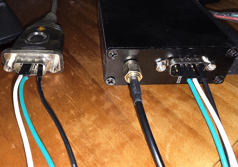
Just to be clear, here is a photo of a quick test wire up. Keeping in mind a proper connection would be better, this is a quick test to clearly show what pin connected to what pin.
Michael,
Appreciate all the information and testing you’ve done to date - no need to do more on my account. I tend to read things cover to cover before I try things and that’s clarified areas where the information was a bit scant or perhaps a little confusing.
I’ll hopefully get some time over the next few days to put it all together. I’m away from home bases at the moment but I’ve brought all the kit I need with me.
3 x Raspberry Pico 2 with OLED displays
3 x RS232 to Serial TTL converters
3 x SX1262 LoRa DTUs + separate 12V batteries
1 x Waveshare USB to RS232/RS485 serial converter
Windows Laptop
Various cables and wires
My ultimate goal is to deploy some of these units in a remote outback location to monitor a range of sensors relaying events back to a central hub (status of cattle troughs, gates, etc) - not a particularly new use case, but a bit of fun. For the moment, I’m familiarising myself with the technology and configuration of various devices. I’ll keep you posted around my testing.
Once again, thanks for all your support.
While I am not 100% sure of you indented/expected setup and data flow, the comment around 3 x setups might mean you miss-understand something.
First key point. Lora, as a base is a point to point system and as is, is not designed to deal with point to multi-point or repeating. This does not mean you cant do it, but normally means you need to ensure it will work.
e.g. If you have 3 lora radios (as in these units), and all settings are the same on all units, then, yes if you send on one, the other two should hear it. But if two send at the same time, then it will either a) the strongest signal will win, or b) both will fail. i.e. lora as a base does not deal with fail transmissions, thats your job higher up the chain/stack.
So if you have two different end monitors and want to send their states to a central PC and they can do so over the distance etc, then you will need to ensure only 1 transmits at a time. e.g. unit 1 sends updates ever 2nd min at 2, 4, 6 … and unit 2 sends at the odd mins, 1,3,5 etc
If you need a relay as the thing being monitored is too far away, then the middle units then needs to be a store and forward, and you will need to do that.
Note: More then happy to discuss specific setups and options.
The key point is not to confuse base lora with things that sit on top of that.
LoraWAN - this is a node to repeater to a server setup. The idea is to setup a base where all nodes can see it. when a node sends a packet it will get to the repeater, that then forwards that to a network/internet gateway/server for processing. LoraWAN has some level of retransmission and packet ACK (that may be on or off) to help ensure the data gets to where its needed, and if two units talk at the some some.
Then there is meshtastic. while many see this as a chat service, it can send packets. meshtastic is good at repeating packets from node to node, allowing very long distances.
Also keep in mind, that these units are store and forward and the lora “speed” may not be the same as your RS232/UART baud rates. lora speed/bandwidth is will depend on its settings, and normally those settings are set to get reliable comms at the cost of speed.
e.g. as and example
src: LoRa Link-budget and Sensitivity Calculations - Example Explained ! - Techplayon

Not how increasing the spread factors lowers the actual data rate. with higher spread factors you will tend to get longer distances.
Also not in that table how even with the low SF of 7, the bitrate is only 5479 bits per second. So a content stream of 115200 bps cant be sustained.
e.g. In one of my play/tests last night, I had one unit connect to the ESP32 debug uart via a UART-RS232 converter and the other into my PC.
while I would get some log lines, and the normal one log line every now and then worked fine, but the when it stormed lots of log data, like at boot, it did loose/drop many.
These units will buffer the data and clock at as it can. If that buffer is full, data will be lost/dropped. So based on the above table and an SF of 7, maybe a baud of 4800bps is a better idea.
Key point/take away, is lora is not designed to be a high data volume/high speed, its design for long distance.
I really wont to stress, that this does not mean you cant do what you want to do, just that you may need to think a little and design it correctly.
edit:
I forgot about the built in relay mode
AT+MODE=1 DTU working mode, 1: stream mode, 2: packet mode, 3: relay mode
But I have not tested or used.
Hi again,
Thanks for the further information.
I should have perhaps noted earlier that I’m ex-IT (originally software development - assembly language through to HLL) with a reasonable networking background, but not at the physical/data link layers. So I’ve been dabbling with microcontrollers and interfacing devices/sensors for the last couple of years (Arduino & now Pico).
So when I said I tend to read things cover to cover, I meant it literally. I’ve been through the information above at the LoRa Alliance, The Things Network and Meshtastic sites to get an understanding of the technology, including native LoRa, LoRaWAN and Meshtastic.
I purchased three units originally with one as spare, but also to potentially test the LoRa Relay node capability if I can’t achieve a functional distance between two nodes. The remote area I mentioned doesn’t have cellular coverage so native LoRa is the go.
As I noted earlier, this forum and your responses have been extremely useful where the product information was a bit scant or perhaps a little confusing, and I was not confident with product compatibility and connectivity.
You’ve gone above and beyond in providing information and apologise if you feel it’s been wasted. It’s definitely assisted/confirmed my understandings and very much appreciated.
All good, help others is never a waste of time.
If you get stuck or things just not clear, feel free to ask follow up questions.
One of the good things with open threads is that while you may not need it, over time other might ![]()
Hi All
I am going a little off topic here but I would like to ask Michael a question and the messaging feature has been removed from the Forum
Hi Michael.
Regarding that cable end pictured
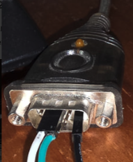
Do you have any history like what it was originally acquired for.
I ask as that is an unusual DE9 back shell with the hex retaining “nuts” instead of screws.
Cables MOSTLY connect to wall or panel mount connectors and have back shells with retaining screws fitted. I have only seen this type of thing fitted to EXTENSION cables (usually pin for pin, all connected) used when say a computer has to be moved for access or to get it closer to equipment racks for diagnostics etc. It essentially moves the panel mount connector to the cable end.
Some back shells are threaded and the waisted retaining screw screws right through and becomes loose in the shell and screws into the hex nut bit on the panel mount connector. These can be either way. The screw can be removed and replaced by the hex nut to achieve the pictured result. I have never purchased a cable configured in this manner. If an extension was ever required we always made it to suit as the length had to be considered and stay within requirements.
I ask because I was interested in why anyone would have a cable fitted with such a back shell just laying around. Note it is only the back shell that has to change. The connector part remains the same be it cable or panel mount.
I note you also have a cross over connection as if both ends are DTE (Terminal Equipment) or is it to correct a cross over in the cable or further back.
I know in a previous post you were involved in there was much confusion with the TX and RX and I can’t remember now if all that was ever resolved (in public that is).
Sorry about the diversion but these days the Forum itself is the only means of contact.
Cheers Bob
1 Like
In that picture, thats a USB to RS232 converter, so should have the “same” interface as you would have expected on the back of a PC. The assumption would have been that the device you want to connect to would use the “supplied” cabled. from PC to device.
As to how devices decide (as we have seen them both) I have no idea.
1 Like