Hey Robert,
Thats done and here s the screenshots.
ChA is + ChB -
Thank you.


Hi Matthew.
That is better. It is what is expected.
The bit that would concern me is the all important DIFFERENCE is not symmetrical. A logic High indicates a difference of full Vcc and a Low should be the same but inverted. However these pics show a difference of only about half Vcc. This I believe is caused by the Pull Up/Down resistors I referred to above. I haven’t got anything to experiment with and haven’t looked closely at the data sheet for that IC. So I can’t be sure. It could be that the DIFFERENCE at logic Low is not great enough to reproduce a Low at the receiver chip output.
It is important to realise that RS485 does not “DO” anything. It is the transport medium and if done right should reproduce at the receiver end exactly what is input at the transmitter end. All addressing, coding etc is transparent to the actual RS485 system and is up to the user.
If it were up to me I would remove those 2 resistors and have another look. Remove gently so they can be replaced if need be. I still am not sure what they are for.
Cheers Bob
Interestingly the circuit in the product Wiki which I copied above shows a MAX485 which is a 5V chip. The IC mentioned in the Wiki text says an SP3485 which seems to be the 3.3V version.
Noe it is possible that these resistors might work OK with the MAX485 but not work properly with the 3.3V version.
If this glaring error is a representation of Waveshare quality assurance I would tend not to trust too much else about that product. Maybe it has not even been tested properly.
EDIT: Another circuit down near the end of the Wiki shows the correct RS485 chip.
Thank you Robert, I really appreciate your help.
I wonder if I’m better off with another product ?
https://www.google.com/search?q=rs+422+hat+for+raspberri+pi&rlz=1C1ONGR_en-GBAU965AU965&oq=rs+422+hat+for+raspberri+pi&gs_lcrp=EgZjaHJvbWUyBggAEEUYOdIBCTk2NzNqMGoxNagCCLACAQ&sourceid=chrome&ie=UTF-8
I am using the RPI Zero 2 W.
A bit about my project. I am looking to generate a NME0183 waypoint message to send to a Garmin MFD.
This is for a rescue organization I work for in NSW.
Regards & thanks
Matt
Hi Matthew
Don’t know. There are probably dozens out there.
You would do well to have a read of the MAX485 and SP3485 data sheets and any application notes. Also the Wiki for this product. You only need the RS485 bits if you are not going to use CAN.
Then do a bit more research to make a decision.
Cheers Bob
A bit more I just picked up. This device is only good for lower speed data as the highest speed is dictated by the switching time of the transistor. This is in the Wiki so have a study of the details.
1 Like
@Matthew281889
What baud have you set the UART on your device to ?
I note reading some docs, it seems the NMEA0183 Mux is expecting 4800 bps ? (If I was looking at the correct documents).
1 Like
Hey Michael,
Yes the python script sets up for 4800.
I think I’m gonna try this hat…
https://core-electronics.com.au/rs485-pi.html
Cheers
Matt
Hi Matthew
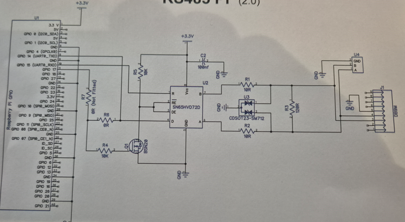
Yes, this one should work. You will note the absence of any pull up/down resistors. It would be interesting to do the above exercise with the CRO measurements for comparison purposes without the resistors.
Be aware the A and B lines might swing +/- 12V when you view the CRO signal.
This device looks like it will handle a respectable baud rate probably due to the use of a faster Fet instead of a bipolar transistor.
This device seems to have a terminating resistor (R3, 120Ω) on board. This should only be used at the cable run ENDS. For intermediate drops it would need to be removed. In your case I think you only have a single circuit with a device at each end so will be OK. I do note this terminating resistor is a through hole type so someone has foreseen the problem and made it easier to remove or fit.
Cheers Bob
1 Like
Hi All
While on this subject I found a must read article.
Which explains the sometimes inclusion of the dreaded pull up/down resistors.
But I cannot see what this inclusion in the devices under discussion achieve. The TX and RX pins are joined and driven by a transistor which employs a pull up resistor so the RS485 device MUCT be in some valid state. Either RX or TX so the inclusion of these “fail safe” resistors should not be required.
This article also mentions that if used there is a reduction of the number of “drops” that can be used. I see no mention of this on any of the texts attached to these devices that I have read. That is people can go ahead blindly assuming that this system is capable of 32 devices. In fact using 4k7 resistors in this role the number of drops is reduced to 9 and the noise immunity offered by a balanced system is reduced drastically. Things will improve if only 1 device in a system had these resistors I think.
In my humble opinion if you are in a harsh environment the better approach would be to not use such a fail safe system so as to gain maximum benefit from balanced lines. Then provide the “fail safe” system in the external circuitry so the A and B lines cannot float.
My thoughts anyway.
Cheers Bob
Hey Robert,
Installed the new hat with NO termination resistor. It’s supplied but not installed by default.
Cheers
Matt

Hi Matthew
Install the terminating resistor. It was the other 2 pull up/down resistors biasing the A and B lines that I was concerned about.
Which trace is the A line and which is the B line.
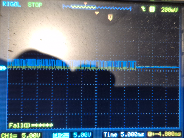
That is not what I would expect. There is something wrong here. How about a sketch of how you have everything connected .
Is that orange arrow on top right the trigger level. You would be lucky to get any sort of a trace with the trigger up there. not a great deal of information on that screen.
Cheers Bob
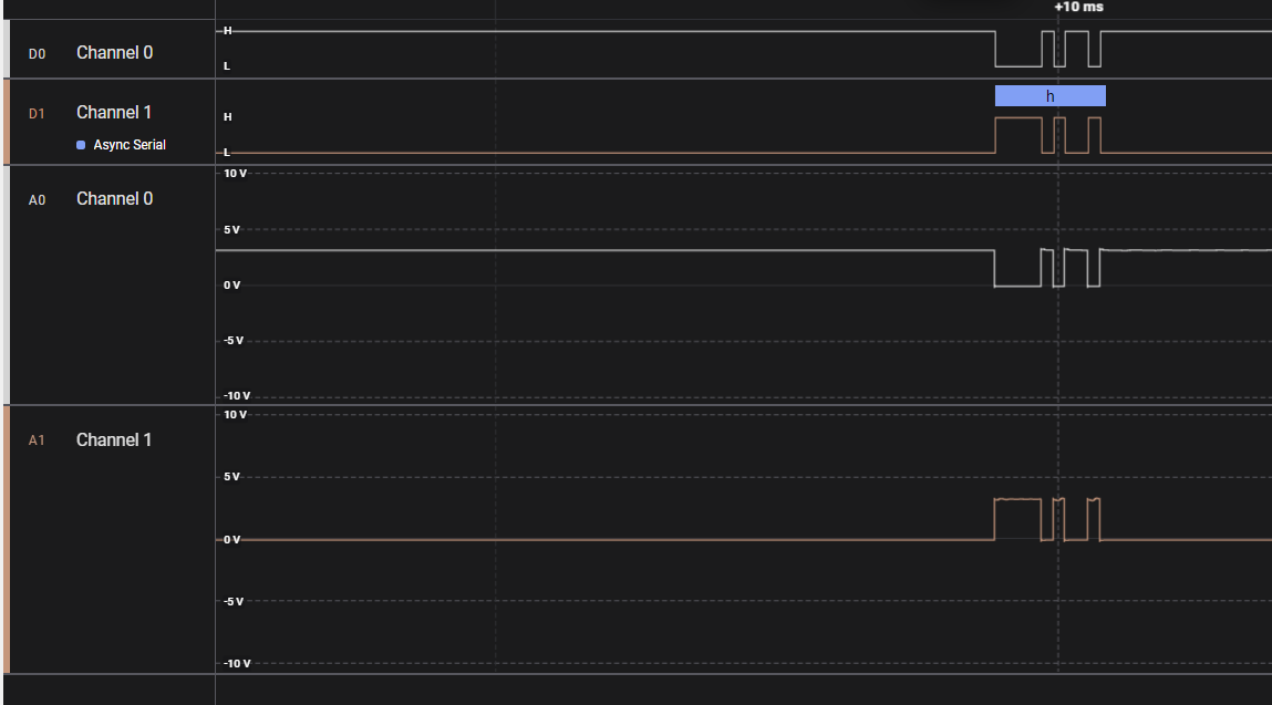
Just to give you an idea of what it should look like for 1 “serial” character, in this case lower case h
This was capatured on a logic analyzer.
Top Channel 0 and 1 are the “digitial” H/L of the A and B RS485 with ref to ground.
Bottom Channel 0 and 1 are the “analogue voltage” recorded, so a bit more of a ripple .
Actual voltages can vary from device to device, but the important bit is which one is higher A > B or B > A
In both cases you can see how A and B are the inverse of each other.

Hi @Matthew281889,
Looks like an interesting project! Hopefully, the combined power of the forum can get it up and running.
To help diagnose the issue, please check the following:
- Confirm the MiniPlex Output 2 is configured for RS-485/Modbus mode.
- Verify your wiring: the Pi Hat’s RS-485 A and B lines should connect directly to the MiniPlex Output 2 A and B lines.
- Ensure a 120Ω termination resistor is fitted across A and B at one or both ends of the cable.
Also, best to confirm that shipmodul is in the right configuration you want (master/slave). Page 74 of the user manual indicates it defaults to master
Let me know what you find!
Hi Matthew
Lets do things one at a time instead of going in circles.
Disconnect “Shipmodul” completely.
Now connect your CRO to A and B lines and show us what it looks like.
You still haven’t clarified this.
Cheers Bob
1 Like
Hi Ryan.
Thanks.
Don’t you mean the “connect directly to the MiniPlex INPUT 2 A and B” ?
Regards
Matt
Hi @Matthew281889,
From the webpage of the Shipmodul that you linked, it has the following:

Page 55 of the user manual has the following also:
Modbus is a widely used industrial protocol between PLCs (Programmable Logic Controllers) and sensors. When this option is set to Master, the MiniPlex-3 can read data from such sensors and convert these sensor readings into NMEA 0183 $YXXDR sentences.
When this option is set to Slave, the MiniPlex-3 will present all common navigation parameters received through its NMEA 0183 inputs in a set of Modbus Holding registers.
When either option is enabled, NMEA Out2 becomes a Modbus RTU (RS485) port to which Modbus sensors or a PLC can be connected. In Master mode, a Modbus tab will be available containing the Modbus Slave table and controls to manage that table. The Modbus feature is described in detail in chapter Modbus on page 74.
I believe when OUT2 is set to Modbus, it acts as the master but there should be the option to set it as a slave if this is required. Hopefully, this resolves the issue!
Hi Robert,
Just the Shipmodul connected to the CRO. No RS485b Modul connected.
CRO Chan A+ input 2 (Yellow), Chan B- input 2 (Blue).
Each CRO channel common is connected to the 12vdc 0v power supply to the Shipmodul (switched mode PS).


Hi Matthew
That trace appears to be green now. What happened to the yellow and blue or is that them as a straight line both at ground.
The green trace looks like not connected to anything and just 50Hz (20mSec) mains pick up. Things would be much clearer if you only displayed the CRO channels of interest. Turn the unused ones off.
That is of no interest at the moment. I meant to connect to the RS485 A and B lines out of the RS485 converter device and show what that looks like. There is something wrong with the result in post 29 and we need to make sure that it is indeed a differntial signal.
Cheers Bob
1 Like
Hi Ryan,
I just thought the Hat could send NMEA0183 messages to input 2 on the shipmodul and then show in the terminal window of the Shipmodul terminal window. Then I could map that input to an output on the shipmodul to feed a Garmin MFD (specifically a Waypoint message). I’m not sure why Modbus is required for a simple NMEA0183 device ?
Is it RS422 vs RS485 ?
Sorry for lack of knowledge here.
Cheers
Matt
1 Like