Hi @Matthew281889 ,
Apologies, the mention of Modbus came from my confusion about your use for this project – it’s not required here.
Following @Robert93820’s request will be the best bet for now ![]()
Hi @Matthew281889 ,
Apologies, the mention of Modbus came from my confusion about your use for this project – it’s not required here.
Following @Robert93820’s request will be the best bet for now ![]()
Hi Matthew
Looks like our posts crossed over.
Looks like both ch1 Nd ch2 traces are superimposed and sitting at about 1.6V which is suspiciously half rail. (rail = 3.3V). Put some traffic an it and lets see what it looks like. Disconnect the Shipmodul altogether so we are looking at the RS485 converter without ANY outside influence.
You STILL have not answered this.
Cheers Bob
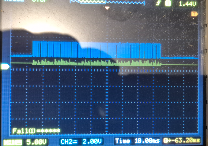
Hi Bob,
Mate sorry for the confusion.
In the image below I zeroed chA and chB on the CRO.
This screenshot is just the HAT outputs A & B to the CRO with the power supply powering the Shipmodul 0VDC as the reference.
There is approx 2vdc present on each channel with no load.
Hi matthew.
OK, now put some traffic on it
I am assuming you still have this plugged into the Pi.
I would have thought that one of the lines would be HIGH and the other LOW as if everything is powered correctly the lines should not be floating. “NOT RE” and “DE” should be either high or low depending on the FET. They both appear to be at half rail V which is a bit suspicious.
When are we going to find out which CRO trace belongs to which line (A or B).
Cheers Bob
Hey Bob Trace A is Yellow + and Trace B is Blue -
Cheers
Matt
Hi Matthew
I can see that from the bottom of the screen. Now I am assuming that RS485 line “A” is yellow and RS485 line “B” is blue. Is that correct.
Cheers Bob
Hi Matthew
We could get there eventually. Now spread it out (increase sweep speed by reducing time / division) so we can see what is going on. That display is useless.
Cheers Bob
Hi Matthew
That is completely wrong. Both lines should swing between 0V and Vcc but 180º out of phase. ie; exactly opposite.
Connect the CRO to the points on the PC board at the end where there is provision for another connection. Marked A, B and Ground. If you are connecting at the DE9 connector you might have something like an accidental short. Connect the CRO ground here also, not to the power supply negative.
Cheers Bob
Hi Matthew
There is something drastically wrong here.The swing is only going from half rail to Vcc on the blue trace (still don’t know which RS485 line this is. Might be told one day maybe) and Vcc while the yellow is only deviating from half rail by a small amount.
Are you measuring at the DE9 connector or at the connection points (holes) at the end of the board as I requested.
If you don’t see fit to provide requested information or confirm measurement points we are flying blind and I would not hope for much success.
Unfortunately I don’t have any RS485 devices here to try to replicate your problem so it is proving very hard with not enough information.
Cheers Bob
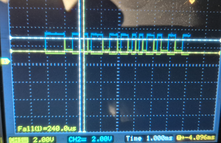
Im not sure if this will help you confirm you test setup/results.
I re-did a quick RS485 capture, but this tome on my old scope.
My setup was simple.
there was no device on the bus, just the adapter.
Both grounds of the probes went to the ground on the RS485 adaptor.
Yellow was connected to A+
Blue was connected to B-
I then sent some data to the device and the following screen image is what it got.
As expected we can clearly see that both are on the same 2V div. and the are the opposite of each other. the left hand markers for CH1 and 2 show the ground level, and the right hand side arrow is just a trigger level.
If we compare that to your image, we can really see the complete inverted signal on the other channel.
So Bob is trying to make sure everything thing is labeled/tagged to ensure what he thinks is A+ signal is actually the A+ signal etc.
Hope that helps make things a bit clearer as an example of a capture of the RS485 output
Hi Michael, Matthew
Yes that is what I would expect to see. 0V to full rail on both lines 180º out of phase.
Matthew CRO pix: Both traces seem to be clamped to half rail somehow. It is not biasing resistors as these are not fitted with this adaptor. That is if he is using the one I think he is. Can’t be sure.
Also the yellow trace is very low on amplitude with a lot of overshoot on the leading edge. Almost as if the CRO is being fed via a small capacitor or the probe is not making proper contact or the actual probe is faulty.
Something is radically wrong here and as this result is similar to the first set of pix I would think something could be wrong with the system preceding the converter.
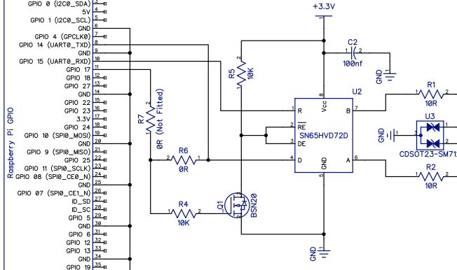
What I would like to see but I don’t know if Matthew is able to do is the driving device removed and the converter just powered from a stand alone supply. Then using a function generator inject a square wave positive going at VCC level into the data input of the converter about 10kHz or so, not critical. Do the A and B measurement again and this should test the converter on its own.
Cheers Bob
PS: I have ordered a few simple converters to have a bit of a play, SKU CE 05154.
I remembered that RS485 unit I had did not have the 120 ohm resister, so I added a 120 ohm accross A and B and recaptured; all other things are the same as the previous test.
I do not that some energy does seem to get sucked out as we can see in the capture the “peeks” seem to now step to about 50%. I also note that with the (1) 120 Ohm resistor (again no other devices) in this unit we dont seem to get to a full “0”.
Hi Michael
I could not find it just now but somewhere recently I saw a circuit of this driver output. The output is push pull so with some load there will be a small voltage drop across the output devices so the output can never get all the way to 0V or Vcc.
I can’t explain the reduction to half rail after what looks to be a predetermined time of about 50µSec. When my devices arrive in a day or so I will have a bit of a fiddle.
What sort of data input circuitry are you using. Something like this wave share “automatic” arrangement like this
Or you using a "barebones " input with the appropriate enable pins activated.
Cheers Bob
All good Bob, just keep in mind, my posts are just to show my findings with the adaptors I have. I don’t have any issue with comms so this is just to show the affects I see that may or may not help with the actual device in use.
I look forward to see your findings with the actual device ![]()
That test is just with my adaptor (2nd one with a 120 ohm resistor).
But, since, in theory the resistor should be a match to the transmission line, which in this case does not really exist, my image might be due a mis-match.
i.e. just need to keep in mind the test conditions ![]()
I will step back a bit so everyone can focus on the actual devices in use. but happy to run any test for comparison if needed.
Hi Michael
It won’t be the “actual” device. It will be SKU CE05154. Really a pretty bare bones board with the converter chip and some resistors.
Can’t see myself outlying lots of dollars just to play.
I think really needs hands on with Matthew’s set up to evaluate what is going on but can’t see that happening but might be able to hack one of the devices I get to simulate what is going on. Will see when they arrive.
Cheers Bob
Hi Michael
The resistor is to match the line at the RECEIVER end to prevent echos. In a simplex or full duplex system the resistor is only placed at the RECEIVER end of the circuits. Simplex 1 circuit, full duplex 2 separate circuits one each direction.
Half duples both ends of the same pair are RECEIVERS hence a 120Ω resistor at each end.
The driver is designed to operate into a max load of 54Ω (not sure, could be 56Ω). In theory this can be made up of 2 X 120Ω in parallel (60Ω) plus 32 unterminated “drops” all in parallel across the line. in practise I believe something less that 32 drops is recommended.
What does the data input circuit of your device look like?
Cheers Bob
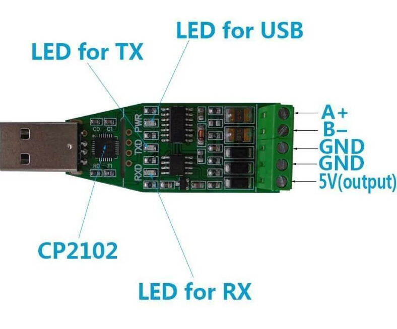
Sorry bob, I have not really looked to closely at the board, its a cheap USB (Serial over USB) to RS485. I got these units for testing and working with OSDP (RFID Readers)
I have a few different units, but that one was the DSD Tech SH-U10 USB to RS485
this image is the layout of the one I have if you remove the case.
And you can get our latest projects and tips straight away by following us on:
![]()
![]()
![]()
![]()