Hi All,
Just wanted to share a simple little side project/modification I’ve been working on. I’ve got a little battery powered heat sealer, which works great but it sure does chew through the batteries and NiMHs don’t provide enough voltage.
My goal is to provide power from an external DC Power Supply, but I want to retain the ability to run it from batteries - I figure this is a pretty common situation for a lot of applications, so figured I’d share it here. With a bit of extra work you could throw on a charging circuit, adapt it for a LiPo and voila - an auto change-over circuit that charges your batteries while plugged in, and switches to battery power when disconnected. There are dedicated ICs for this, but I prefer the fully analogue approach, particularly because the parts are available locally.
I opened up the heat sealer and drew up the schematic:

A quick check with the multimeter showed the battery voltage drops from 9v down to ~7v when powered on. I ran the element from my lab supply set to 7v and it pulled about 2.2A. At 9v I nearly let the smoke out with 3.3A! It worked ok at 6v but wasn’t great.
So I’m going to need a supply capable of at least 15W and about 7v - not very common. I considered using a buck converter and just using a 12v plugpack, but there’s not enough space inside for the regulator, I’d still have the issue of possible reverse current through the batteries or the regulator, and it wouldn’t stop the batteries providing current while power was attached.
Often you can get away with just diodes on each line like graham showed here when you know the PSU voltage will always be higher than the battery voltage. The tricky part in my case is that both power sources overlap in voltage - the 6xAAs will range from ~5v when nearly flat and dumping current, to ~10v when fully charged, but I don’t want any significant current being pulled from the batteries if the PSU is connected - no matter what the battery voltage.
A relay was out of the question due to space limitations.
After a bit of mulling over it, I came up with this simple circuit modification: https://tinyurl.com/y5zq2dfl

The PSU diode serves a dual purpose - reverse current protection for the PSU, and it keeps the P channel MOSFET on when a PSU is not connected - else the battery would be bouncing between on and off or the MOSFET would be in its saturation region and limiting current significantly (and also getting very hot). The diode on the battery line is just to prevent reverse current through the batteries, while the 10k pull-down resistor means that as soon as V_psu is disconnected, the FET turns on and power is provided by the batteries.
Note that you don’t want a FET with a super low Gate Source Threshold voltage - in this case we want something with a threshold voltage more than the maximum difference between our batteries (~9.9v max) and our PSU (~7.5v). So we’re looking for a Vgs of > 2.5v, but less than the minimum supply voltage of ~5v. If the Vgs threshold voltage is less than this and our batteries will start to drain even with external power connected, too high and the batteries won’t be able to fully discharge.
If you were going to power electronics from something like this, it’d be a good idea to include a capacitor to smooth out the switchover transients. In my case I can get away with it, because the heating element is just a bit of wire so who cares if it has a bit of a voltage spick or dip.
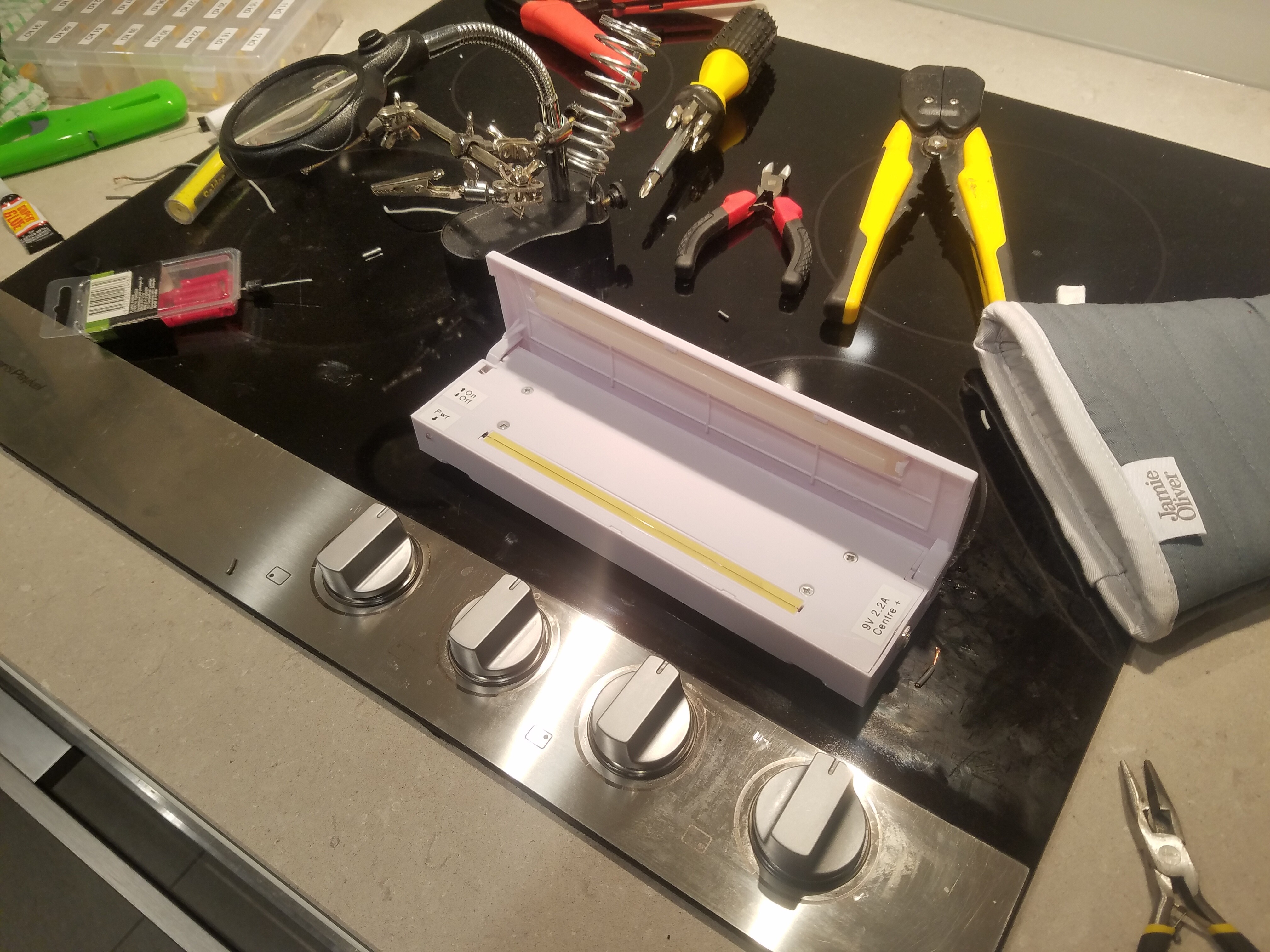
Here are the parts I’m intending to use:
(These are a bit pricey, but I already have one laying around and I can set it to 7.5v - perfect! With the 2.25A continuous supply limit, this should be able to keep up with the heat sealer’s demands. I could also add a buffer cap on the supply side to help it out with inrush current, but that just adds unnecessary complexity for this application.)
https://www.jaycar.com.au/6a10-6a-1000v-diode/p/ZR1024
These diodes have a low forward voltage and can handle up to 6A! Given I’m running more than 2A through these, I want the lowest forward voltage possible, to minimise heating. The R6 package is a little big, but it still fits easily enough so it does the job. 
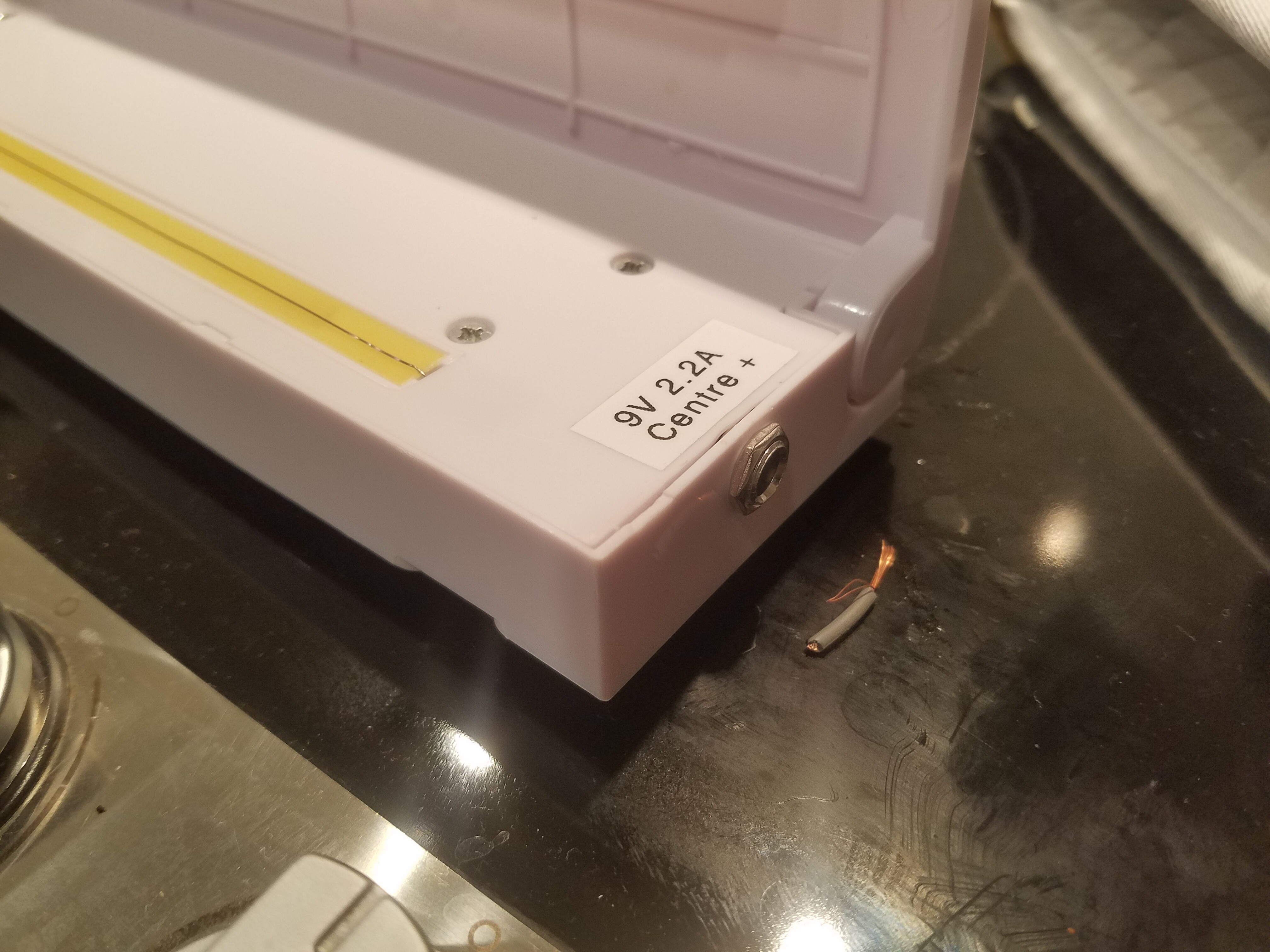
https://www.jaycar.com.au/2-1mm-bulkhead-male-dc-power-connector/p/PS0522
Got a better idea? Let me know How would you have handled this?
 Gotta work where I can in an apartment.