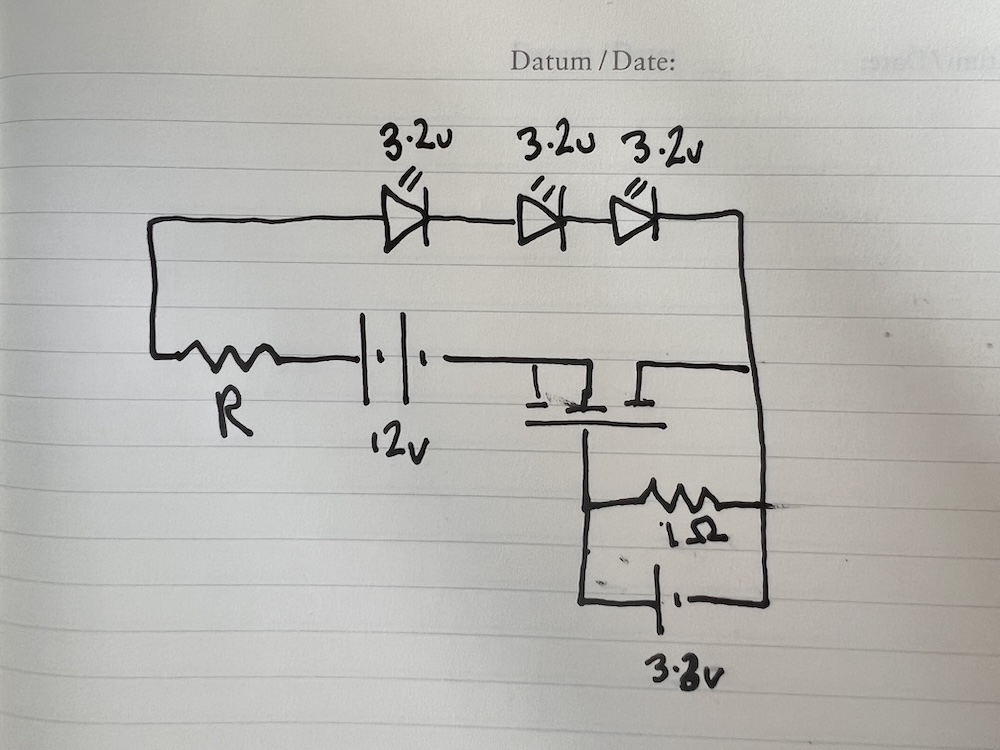
I’m trying to make a set of strobe lights for an experimental aircraft. I will be integrating position lights but I want to sort out the strobe function part first. The strobes will sit out in the ends of the wings and while figuring out what I need I’ve hit a few issues and would appreciate some help. I’m new to all this so please be patient. I’ve uploaded an attempt at a circuit diagram for what I’m looking to do for each strobe. Each strobe unit will consist of 3 LEDs in series. The forward voltage is given as 2.8 to 3.2v so I’ve assumed 3.2v for each (9.6v total). The data sheet for the LEDs says they are 1.5amp units (yes, they are big…and bright) all powered by a 12v source. So based on Ohms law, I calculate that the resistor R in my diagram should be 1.6ohms (correct?). To turn them on ie flash, I was planning to use either an N channel mosfet such as the IRB8721 or a misfit power controller such as DFR0457. The gate would be controlled by a RP Pico with a small resistor. the DFR0457 seems like an easier solution.
Next, using Ohms power equations, I get all sorts of different results. Overall, I get P=IV = 1.5amps x 12v = 18watts (correct?). Next for the resistor, do I use P=v^2/R or P=I^2 x R? Using the first equation, the resistor would be 90w but using the second, it would be 3.6w. So, which is it? Do I need a monster power resistor at 90w or do I need a more modest 5w resistor?
Now, the same RP Pico that is controlling the strobe would turn on and off the position lights which are fairly straight forward LED lights that are turned on when you start up and turned off at shutdown. The challenge is that I want to minimise the number of wires running out to the ends of the wings. more wires = more weight and although it isn’t much, it all adds up. So my main 12v supply would power the strobes and also supply the simple position lights. So, as I see it, I have 3 functions at the ends of each wing (strobe, coloured position light and white position light). Now, the challenge is how to turn these on and off from the cabin without running lots of wires out to the wingtips. So, one solution would be to run the 12v supply out to the wingtips, as well as 3 signal wires used to pull up a pin on the RP Pico out at the wing tip. Could this be dropped to the 12v supply and a single wire with a PWM signal? If so, would that mean I need a single RP Pico to inform the wingtip RP Picos which LED lights to turn on or off via a PWM single? My apologies if that is overly confusing or if I am overcomplicating this, which I probably am.
Thank you in advance for any input you can give.