Can I use a 2N7000 NFET? I have a few of them.
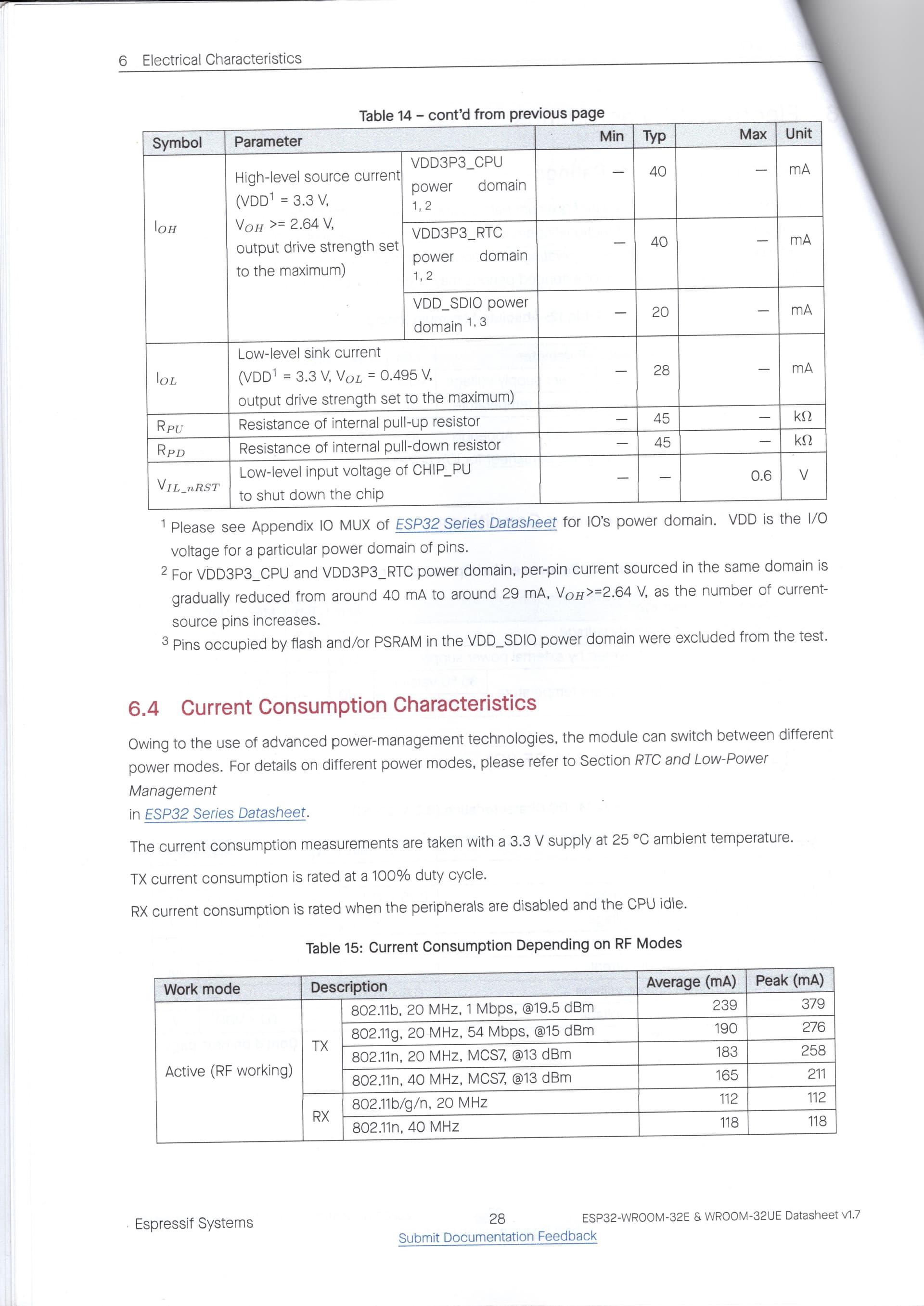
Also, here is p27 of the ESP32-WROOM-32E datasheet. It suggests up to 40mA.
Can I use a 2N7000 NFET? I have a few of them.
Also, here is p27 of the ESP32-WROOM-32E datasheet. It suggests up to 40mA.
Hi Gerard
As I suggested above, you can try that circuit.
But NOT to switch the solenoid directly. Not enough grunt.
That data sheet certainly does say 40mA is if you want you could drive the TIP directly. Refer above.
Cheers Bob
Just checked, my blunder I did mean to print 2N7000. Don’t know where the extra 2 came from.
I do have some IRF1405 MOSFETs though.
Hi Gerard
A very high current device. By no means a “logic Level” device though with a gate threshold of up to 4V, and 5V is way down the drain current curve. Would take 10V + to turn it anywhere full on. I personally would not use it in that application
Cheers Bob
Yeah, you’re right. I did some checking and it seems the only way to get it to work is with a gate driver like a TC4420.
I’ll do some tinkering with your circuit tomorrow.
My software guy is all over me for a solution!
Which is understandable since I’d be all over him if the problem involved software!
Hi Gerard
Now we are cooking. I am pretty sure I mentioned these dedicated Mosfet Drivers previously.
I have not used this particular one but I have used others in the past. They remove just about all Mosfet drive problems. (except high side driving with N channel devices but that is not a problem here). Be aware though that these (the ones I have used anyway) are designed to supply that 6A of current for a very short time just to charge up the Mosfet Gate capacitor so you will still need a Mosfet.
The good thing about this is it only has a quoted 10µA input current so you can drive it with just about anything and input switching range is well below 3.3V so you should be able to drive it comfortably directly from your MCU and have isolation. Fit a resistor between the MCU output and this device input to limit Max MCU current, Insurance they call it.
Connect VDD to your 12V and you should be able to switch any Mosfet you can get hold of. Check data sheets though as the “logic level” ones as on Core site will not like 12V. Easy fixed though, just connect VDD to 5V. Fit about 100Ω Gate resistor just to steady things up a bit.
Cheers Bob
Hi Bob,
You are sure to have mentioned it but I’m a bit slow on the uptake sometimes!
I cannot find anything suitable on the Core site. I really need a package of some sort rather than a tiny PCB. I’m constrained by cost…
I can get a DIP version of the TC4420 from DigiKey but the wait time will not be good even though they have Aussie stock.
Hi Gerard
Element 14 have 2 through hole models. Not much difference except for temperature range. Funnily enough the cheaper one has the better temperature specs.
Stock codes 1292284 and 9762566. Postage is a bit sexy though but normally only a few days delivery even from UK. I think they might have their own courier system.
IRLB8721, SKU ADA 355
This looks like a “logic level” device. looks like it is almost fully on at 5V. full on at 8V.
Cheers Bob
Oh right. It’s all in a TO220 package then.
Hi Gerard
I wish you would be a bit clearer on what you mean. Is WHAT in a TO220 package??
The IRLB8721 is in a TO220 pack, the TC4420 comes in a variety of forms, refer Element 14 web site for details. The stock codes above are DIP8 form that is through hole 8 pins (“normal” IC) which I am assuming you prefer.
While we are here. Another alternative you might consider is a module which Core stock.
An Opto coupled high side switch driven directly by your MCU (3.3V logic). This means you switch the 12V instead of low side switching to ground. The Opto coupling will give you isolation.
The down side is this is a small board and the interface is a “Gravity” connector but I am sure Core would sell 3 wire cables with a connector fitted that would suit. For this application ignore the centre connection.
I think I have suggested this as an option previously but you wanted to stay away from add on boards. Given the present problems regarding finding enough current to drive anything This option is not looking too bad at all. Everything is done for you on the board, just connect MCU point and ground, 12V in and out and you are basically there. Can provide a connection sketch if you decide on this option.
Cheers Bob
Cheers Bob
Apologies, yes, the IRLB8721.
The opto isolator is worth looking at. Is it SKU: BOB-09118 ?
Gerard
No. I had looked at that. It is a dual isolator but has a high source resistance of 10k, twice that of your level converter. That is no useable current capability.
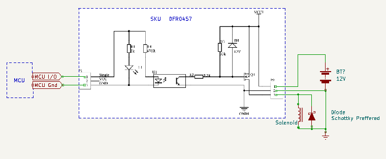
The Gravity high side switch I am talking about is SKU DFR0457. Sorry I omitted that. The schematic for this is linked at the end of the product Wiki page, linked on the Core page.
Cheers Bob
Oh that is ideal and the price is right too.
Core have a similar product that use the I2C (IIC) bus. SKU: COM-15093. We tried one of these but it looks like there’s a bug in their firmware which causes the I2C bus to lock up. Too expensive too.
OK. Will post a circuit shortly
Cheers Bob
Hi Gerard
As promised a circuit for you
Explanation of “overkill”: When the mag field collapses at switch off there could be much more that the applied 12V generated. This in turn would mean a lot more than the 0.5A operating current. This is only present for a very short time but it will be there and the idea of using a Schottky is they will be fast enough to catch it before any damage can occur.
Cheers Bob
I have been using a BAT46 diode. 750mA for <10msec.
Hi Gerard
Pretty borderline. I am surprised it has lasted this long. Lucky I guess.
This is pretty important to have enough in reserve. If it fails the switching Mosfet is very likely to follow pretty quickly. Mosfet in this application tend to fail short circuit so your solenoid would be permanently on.
Just looked. That 750mA is Absolute Maximum rating and continuous Max is 150mA. It is listed as “small signal” not really for power use. I definitely would not use it here. In this situation to go bigger is better / more reliable.
As damage to this sort of thing is cumulative I would bin this one and not use it for anything else.
Cheers Bob
PS: I just noted you did specify BAT46 in your original circuit. Sorry, I did not pick this up earlier. Getting a bit slack in old age.
Yeah, makes sense. When I did electrical theory at Uni, I was surprised at how much energy came from a collapsing winding like a solenoid in the first few nanosecs.
Lucky you went to Uni. I had to finish school at 15 (intermediate certificate 1950).
Cheers Bob
And you can get our latest projects and tips straight away by following us on:
![]()
![]()
![]()
![]()