Unable to receive data/configure SX1262 DTU

Its all good bob. Your input and comments are all very valid and helpful.
As per my other post, I hope to test the RS232 settings over the weekend. Then we can confirm how it should be.

Part of the challenge with this one is the wiki is both correct and incorrect. i.e. You need to read it all and see what should work with the firmware installed on the units in use; as it seems the default behavior has changed over time.

Hi Michael, will do. Everything looked fine from what I recall, except the baud rate which was 115200 not 9600

Hi Michael
Just for interest what is RS425.

I know of RS485 and RS422.
But RS425 ???
Cheers Bob
By the way, I googled “RS425” and came up with all sorts of things but not a Data communications system.

Sorry, my bad and good pick-up, it should have been RS485.
the unit supports RS232, RS485 and RS422
I have updated the post to correct.

Quick update for today.

I am now running on the RS232 interface. Its as per the wiki, a stock DE9 interface for RS232. I made up a pair of 3 wire cross over cables to go between the PC USB to RS232 DE9 and the Units DE9.
i.e.
Pin 2 to Pin 3
Pin 3 to Pin 2
Pin 5 to Pin 5

A new thing that I found, that i have not seen in the official wiki yet, is the “key” button press to rotate from RS485 - RS232 - RS422 - RS485 … is not saved, so any power cycle or unit soft restart will revert back to the saved interface.

As such, the “key” press is really just to get it to an interface where you can talk to it, then +++\r\n to get access to the AT Commands, then set and save the settings you want.

Its unclear what the defaults are (again) is seems this may have changed over time. For my units on V1.3 the default was RS485 9600 baud 8N1. I have seen the reference to RS232 115200 baud 8N1 (as per what @Taylor94043 found) in the wiki as well.

Hi Michael, Taylor.
I must read up on this LoRa stuff when I get time. We are having some family drama at this time, namely my younger brother is very ill in hospital.

I am a bit confused. You guys seem to be talking as if the LoRa device generate its own clock and you have to set baud rates etc.

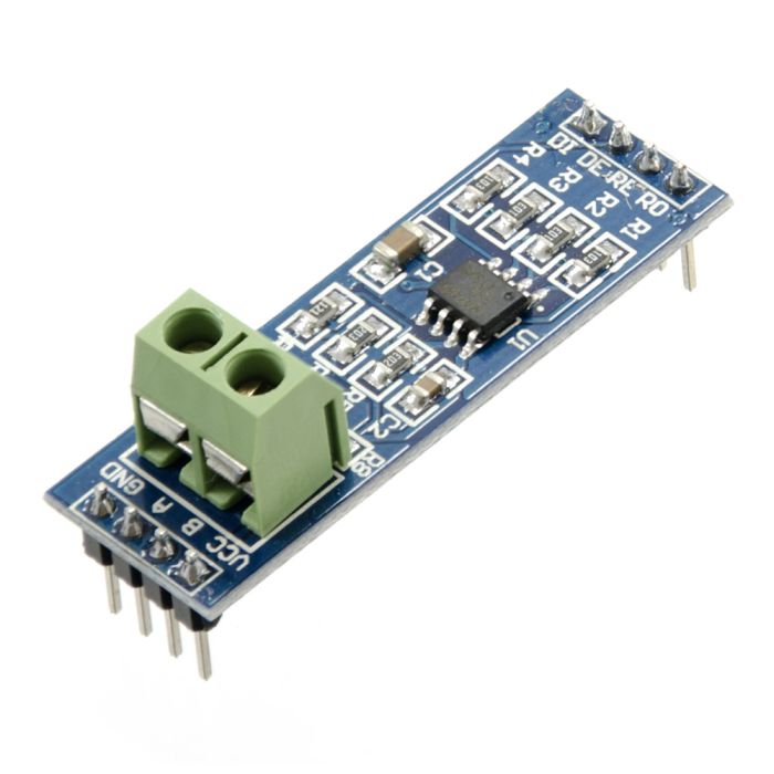
Surely as a carrier system it will accept whatever is put into it with possible maximum data rates for different inputs. This is understandable. I also understand it will accept data in RS422, RS485 and RS232. This has to be set which I also understand.

So you input data using whatever system and the RX end gives back to you whatever is input at the TX with the same system (Rs422,485, 232). Then it is converted back to whatever is required so the RX end deciphers the data and does its thing.

Whatever the actual traffic should be in the “I don’t care” category as far as the transmission is concerned.

What I am getting at is if the LORa devices started generating their own clocks surely this a recipe for disaster. Surely the LoRa is just the carrier medium and maybe those baud rates quoted might be the maximum allowed for the particular “RS” system in use.

In other words say the selected system is RS232. If you applied a Positive voltage between pin 5 and the TX pin on the DE9 connector I would expect to see a positive voltage between pin 5 and the DE9 RX pin at the other end. The same for an application of a negative voltage.

So you generate a Data signal at one end within the LoRa baud rate limitations. Apply that signal to the LoRa TX pin at the sending end. This data signal appears on the RX pin at the Rx end and presented to whatever the equipment for processing or other required action.

Provided this at a speed is within the LoRa device limits it should be completely transparent to this equipment. In other words it doesn’t care what the data is or the baud rate. Whether this data is understood or not should be up to the actual terminal equipment.

I think this data should be inserted INTO the LoRa TX pin and recovered OUT of the LoRa RX pin.

This is my interpretation on how such a system would work. I have had no experience with this LoRa but I have had experience with many other Microwave coms systems. The terminology used “back in the day” was “Line” side and “Equipment” side. Equipment referring to terminal equipment of various flavours and could even be a telephone. Line was as the name implies the “Line” leaving the premises and could be the input to a pair of wires or the input to a microwave or other radio or transmission medium.

Thus the term “Transmit” referred to a signal leaving or going away from the terminal equipment or operator and “Receive” referred to any signal incoming to Terminal or operator. This terminology was maintained IRRESPECTIVE of which direction the signal was presented to any intermediate processing equipment.

This is why I believe the INPUT to the LoRa should be the DE9 TX pin and the OUTPUT should be the DE9 RX pin.

Could be wrong with all this.
Cheers Bob

Bob, in short lora is a spread spectrum RF protocol that will TX packets. This does in fact have have bandwidth, spread factor (plus coding rate for error detection); these factors can be used to calculate a “bits per second” rate of actual data transfer between a lora tx and rx node.

A device can use this base lora to send and receive data packets. These packets can then be encoded/structed and encrypted (or not) based on any defined setup, as long as both ends are doing the same thing to create packet with the user payload and reverse it.

The actual input “serial” interface and lora transmit rate are NOT related at all; e.g. you can have a RS232 9600 baud device send to a web site via a gateway. There is no need for the gateway to have an serial ports.

With this specific device we can think of it as 5 independent steps.

  1. A device that wants to send data is connected to this SX1262 via one of its inputs (in this case RS232, RS422 and RS485). The device allows the end user to set the baud rate, parity etc to what ever the user wants for the comms between the tx device and THIS unit. e.g. 9600 baud, 8 data bits No parity 1 stop bit.
    Key note: this step gets the data form the users external system into the SX1262 DTU TX Buffer. e.g. from a pi, micro controller, pc etc.

  2. Now that the data is in the SX1262 Buffer, the SX1262 will format and encode this as defined inside the unit. Some settings are user defined eg encryption. This step is dependent on the devices in use; the can stick to a standard like loraWAN or create a custom one like this device.

  3. The encoded data is then transmitted over the air via lora using the devices (user defined) settings (e.g. Spread factor, Bandwidth, code rate and frequency).

  4. ANY device with the same Frequency, Bandwidth, Spread factor etc within range will hear the signal and start to receive it. Smarter devices will drop the RX as soon as they know its not for them; most I have seen will RX the entire packet into a RX buffer for processing.
    At this point we now have the encoded from step 2.

  5. The RX unit will then decode (e.g. remove encryption etc) and see if the packet is for “this unit”
    At this point the clear data packet is in the SX1262 RX buffer ready to send to the remote end users device.

  6. The remote end uses device will be connected “they way the user wants/needs it to be connect”; not this has nothing to do with the way the TX device connected (from step1);
    There is no reason at all for the device to be the same as the one in step 1 nor have the same settings/bit rates. The STX1262 will simple send the data out the defined interface at the define rate.
    i.e. there would be nothing stopping a hardware hack to tap into the TTL side of the RS232 chip to allow direct connection if they were happy to open the box and solder some wires.

The key point is each step is independent of the previous; its a “rx, store and forward” not an end to end “RSxxx” wire.

If the end user wanted to pretend/emulate it was (for example) an RS232 end to end device, then they could set it up that way, but there will be a delay between “packets”; where each packet could be up to 240 (from memory) lara limited bytes. (I have not yet check the max buffer size of the device and if it breaks up bigger packets into the max lora size.

Since it is a store and forward with processing delays and radio overhead, it is possible to overload the input buffer and have data loss.

most of these devices have thier own micro controller that does all the custom “smarts” between the external I/O and the lora radio module.

think if this as 100% digital and with a buffer of data moving from one step to the next.

It can be a bit full on and confusing while learning about lora. What does not help the new kid is there are standard systems using lora like loraWAN, then there are end user custom setups where the designer defines how their device will work to tx/rx over lora radio.

I hope that helps.

2 Likes

Hi Michael.
Many thanks for that. Explains a lot and makes things a bit clearer.
All this LoRa stuff and other strange things have come about since I worked full time and I have not realy made much attempt to keep up.

I was trying to relate to my own experiences. Most of my work was with the actual radio (Microwave etc) link where all the packets, error checking and such was done prior to insertion into the “line” (actual radio link) and the unpacking and checking done after the radio. The “Line” equipment was really only the transport medium which with a bit of luck (and management) spat out of the receiver exactly what was input at the transmitter. The rest of the clever bits were done externally to this.
The only processing the Line system would do would be to modulate one or more sub carriers before final modulation to enable multichannel operation. But Even that is done prior to the actual radio. At what was termed “Baseband” level.
I think this might be how Core’s little point to point radio link works. I have not looked at that much either.
Many thanks again
Cheers Bob

1 Like

Hi Michael
If the LoRa is as you say (and I believe it is) then would it be possible to test end to end by inserting a pulse stream into the TX pin at a suitable rate and level (+ and - for RS232) and say about 30% duty cycle (so you can check for any possible inversion) and make sure the same stream comes out of the RX pin at the other end. A function generator would be good here. Also an oscilloscope.

This would eliminate the LoRa from possible problems. Like get this bit working first. It appears to me that an attempt is being made to trouble shoot this while trying to run a whole system. There are a few cross connection possibilities and other bits to cause the system to not work I think a break up is needed otherwise you are likely to be a long time finding out what the problem really is.

Cheers Bob

1 Like

Maybe. To me there are 3 key bits.

  1. Is the end device and its lora unit talkimg to each other.

Since he can get the AT commands to work, that should be a yes.

  1. Are the units talking to each other… ie is the lora radio working.
    Since the tx led on one unit flashs and then other units rx flashs, this hints the lora radio side should be working and the tx devices is sending normal data ok.

  2. Is the rx getting data from its unit.
    This seems to be the issue.
    The main reasons for this bit would either be wromg comms settings, eg AT working from.PC but not pi or whatever. Or the encryption is different. Or running in different modes. Eg one strraming and one relay.

As such i wanted to see the config from.each device and we can reset the encryption and re test.

I did not that at the start of this issue there were some device to unit comms issues, which i beleive have now been resolved.

If so and based on the feedback so far in think we could.be done to the units config.

1 Like

Just for reference (sometimes a visual of the board helps)
here is the component side of the PCB for the SX1262

I did not mark, but there are 3 LEDs on the left of the lora module
these are power, TXD and RXD.
The TXD/RXD LEDs are run off the ARM processor, so if the RX led is flashing as expected, then the ARM processor must have gotten something.

edit: I forgot to mark the RS422 and R425 driver chips, which are the two on the right hand side of the RS232 driver.

1 Like

Just an FYI.
The SZ1262 DTU offers 80 Channels ranging from 850Mhz to 930Mhz
Since lora in Australia should be AU915 to ensure compliance the channels should be selected from 85-78. I run some tests with my spectrum analyzer and confirmed the following table I built seems correct. i.e. CH 0 was 850Mhz, CH 66 was 916 Mhz (keeping in mind the nature of spread spectrum).

In my table
Blue: Channel No.
Red: Outside the AU915 range
Green: Inside the AU915 range

Side note: most references to the frequency range valid in Australia is based on the loraWAN documentation. So I have made the assumption the base lora frequencies are the same.

"…
The 900 Mhz band in Australia is used by both Optus and Vodafone currently for 3G.

There’s a small segment 915-928MHz allocated for LIPD (which includes LoRa)

https://www.legislation.gov.au/Details/F2023C00524
…"

From the gov.au page

  • All transmitters - 915–928 - 3 mW

image

edit: For those that like a little more proof of test or the tech stuff.
The Spectrum chart (yellow) peek hold ( 915 - 917Mhz).
We can see that channel 66 is spot on centered on 916Mhz

2 Likes

Hi Michael.
Just for interest maybe the reason for using that frequency range is the very good scattering effect this has.
In fact it is this range that is used for “Tropposcatter” point to point systems.
Cheers Bob

1 Like

It should be linked to the bandwidth set (125kHz in that example), which looks to be about +/- 125Khz/2 (200K per division). If I set the bandwidth to 500Khz, it uses more (as expected). How much of that is used (in any one transmission) is then linked to the spread factor. e.g. SF 7 has less error recovery “transmissions” but allows faster data rates, SF 12 has more copies over that range, so slower rates but higher chance of data recovery. So to get a good “coverage” of the air space used, you need to let it run (with peek hold) for a reasonable amount of transmissions (same approach you would use to see wifi usage).

In that image, I was more interested in the center frequency to ensure my translation from the SX1262 DTU channel to actual frequency was correct, and it was 100% on target (Need to make sure we stay legal, so good to verify if we can).

1 Like

Bob, i have collected some data and confirmed how this lora module works.
If i send the test data “test\r\n” the uC creates a bigger data packet with an Address and Network ID.

Addr NetID ?? [ t  e  s  t \r \n]
0000 00    11 [74 65 73 74 0D 0A]

The uC then sets up the transmit via a series of packets over SPI to the module, then tells the module to send.
So for this setup their is no simple way to just send a signal; i.e. you would need to inject the correct SPI commands. So confirmed, as far as we are concerned its all just packets of 1 or more bytes. that said, while I still need to check, I suspect the module gets a GPIO pin setup as an IRQ signal pin to tell the uC there is data to read. If that is true, then a simple monitor of that pin would show the lora module has RX’ed and is ready for that to be pulled by the uC.

It also shows that there is a 4 byte overhead when sending data, so if sending 1 byte at a time will create 4 bytes of over head per byte. To increase transmit efficiency bigger packets will yield a higher data to overhead ratio.

The module supports IRQ, but only as an output from the module to the uC. As the module operates only in slave mode over SPI, the uC can send a message at any time (after checking for not Busy) and the module should be listening - an interrupt is not necessary to start a communication.

If you can get access to the SPI you could monitor it with a logic analyzer and decode the messages.
USB Logic Analyzer - 24MHz/8-Channel | Sparkfun TOL-18627

Thanks Jeff. Yes I have already connected my logic analyzer to the SPI and can see the comms. What Bob and I were talking about was without special tools, could you test the lora to lora bit, as the OP seems to be able to TX but not RX. I was just confirming it was more structured and needed complete setup and data to be clocked in/out over SPI.

On a side note, do you happen to know the exact uC on the SX1262 DTU ? so far I have not found any match’s to the number printed on it.

edit: I think I found it

GD32F103CB56 (or 5b) CB makes it a 128Kbytes so an Arm Cortex M3

I believe Taylor (OP) was going to update to the latest firmware. But as per the documentation, you need the RS485 to update the firmware; which he is waiting for atm.

Hi All.
Just had a bit of a blouse at this thread more or less from the beginning.

Michael. You said earlier that this system defaults to RS485 and you had no trouble getting it to work. I think that is what you implied.

As I said before RS232 can be VERY confusing when it comes to TX / RX terminology.

My humble suggestion at this stage would be to scrap RS232 for the time being. Get a couple of RS485 - TTL converters and try that. If you had no trouble then maybe that might be the way to go.
MAX485 - TTL UART to RS485 Converter Module

Skip to the beginning of the images gallery

MAX485 - TTL UART to RS485 Converter Module

I am still under the impression that it is the TX / RX confusion that is a good part of this problem. RS485 would at least solve or confirm that and verify that at least the terminal equipment is working.

Failing all that if this is only point to point and a reasonable distance the simple little RF transceiver by Core might be the answer.
Cheers Bob

Yep, 100% bob. Default is RS485. RS232 is as you expect 2/3 Cross over and 5-5 (9 Pin); and yes RS232 signal levels as you would expect.
But you do need the RS485 for firmware update.

While the updates (and default) are RS485, I would not leave it that way for production, unless thats what you wanted.

I found a small bug. If you send a packet to it that cant be decoded (e.g. different encryption key) the uC seems to put the RS485 into TX mode, ready to send the decoded data; but since it cant decode, nothing is sent. But the RS485 side stays in transmit mode. Now you cant send data into the unit until reset and goes back to RX mode. It will reset when it gets a valid packet or a power cycle; Keeping in mind lora is public use space, there will always be a risk that some rouge lora packet arrives at the unit leaving it in TX mode.

This does not happen on the RS232 (or RS422) interfaces; just the half duplex RS485

I think we know have a firm understanding of all the parts and how they should be wired and setup. As such let see if the firmware updates fix the issue.

Hi Michael

Not Always. Only DTE to DTE (Data Terminal Equipment). That would be computer to Computer, “Computer” in this case being Arduino/Converter combination. DTE to DCE (Data Communications Equipment) is pin to pin. That is what is the TX pin on the LoRa is just that. The TX signal INTO the LoRa. As the RX pin at the other end being the received signal OUT of the LoRa.

Taylor in the past has said that nothing comes out of the TX pin on the receive LoRa. This to me would be normal as I believe the signal comes OUT of the RX pin. I believe the LoRa devices are DCE things.
In all of this I have not seen much mention of the pin connections that ere ACTUALLY used. Has anyone had a look at the RX pin on the receiving LoRa. I have only seen any mention of the TX pin so I don’t know personally where this problem is at the moment.

I do appreciate your in depth (in layman’s terms) explanation of the LoRa system. All this was most informative. Even enough to want me to stay well clear Ha Ha Ha.
Historically I am basically an analog person but through large project work have had quite a lot of experience in the installation and implementation of some of these networks, both RS232 and RS485. I have had a fair bit of experience with transmission lines so understand the use of terminations etc in RS485 systems, balanced lines etc.

But Analog and digital DO cross paths in many instances and one complements the other. So over the years I have picked up enough about digital to appreciate the systems and I suppose you could say enough to be dangerous. But as for the hardcore nitty gritty at my stage in life (88YO) i will leave that to others. My attitude over many years (successfully) has been “give me your digital, I will transport it from A to B and give it back to you”. Worked pretty good.

One bit of trivia you are undoubtedly aware of. There is no such thing as “digital radio”. Just a marketing phrase.
Cheers Bob

1 Like