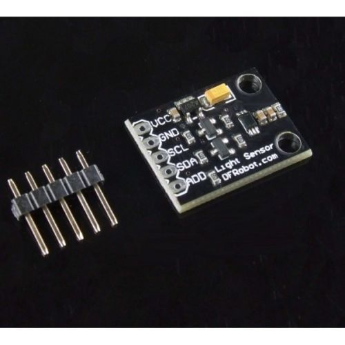
This is a BH1750 light intensity sensor breakout board with a 16 bit AD converter built-in which can directly output a digital signal, there is no need for complicated calculations.
I have purchased a BH1750FVI Digital Light intensity Sensor Module (GY-30) and soldered it myself. I’m facing problems connecting to it, it’s not getting detected, I either get a fixed value 54612 or device is not configured error message.
It looks like the output value always being 54612 may indicate that the sensor isn’t actually properly connected, so the changing state of the results you’re getting might be because of a weak connection somewhere.
In terms of getting the ‘not configured’ error message, this could be from the lack of an initial configuration for the sensor in your code, which is normally done through some sort of ‘begin’ function.
Would you be able to provide some pictures of how you’ve got things hooked up and of what code you’re running? Keen to get help you get this one fixed up.
I ran your code as well as this example from DFRobot on an arduino Uno without any problems on our end.
The only thing I can think of that could be causing some issues is not having similar length of wire for the SDA and the SCL wires could be causing some signalling issues.
I’d recommend trying to to use similar length wires for both connections.
I went to github to see if anyone has had this problem. Have a look at this thread on Github where a few people claim a code excerpt solved this problem.
The device must be at address 0x23 or 0x5C - it seems there is no way to change this. 0x23 is the default. If you are not seeing it at this address then your I2C is not working. Check that you have SDA and SCL the right way around. Also check that all the connections are working properly - it is common for a breadboard to develop loose or intermittent connections over time. Try moving everything to a slightly different location. Try running the connectors directly rather than relying on the power buss (some breadboards are known to have breaks in this buss).
54612 is the maximum value that can be returned. It is a calculated value, so that indicates that it has been working, albeit imperfectly, at some point. That also points to poor connections.
Hi Jeff, I have a similar problem with the sensor BH1750.
But my device is at address 0x6A , not 0x23 or 0X5C. Is still alright if i do not get the message “Device is not configured?”
Thank you very much
The BH1750 chip can only be addressed at 0x23 or 0x5C - this is built-in to the chip by the manufacturer. The only way it could appear to be at a different address is if you are connecting through an intermediate device, such as a multiplexer. How did you decide that yours is at address 0x6A? If you get the message “Device is not configured” then it will not work; if you don’t get the message then it might work, depending on how that intermediate device is configured.
When i am using, in the code, the addresses 0x23, 0x5C, 0X60, 0X7E- i get the error message : “Device is not configured!”
If i use the address 0x6A, i don’t get the error message, but instead the light intensity is 0 (and sometime some different values, but i think these values are not real values, maybe errors values: 17 lx, 666 lx, 853 lx, 7492, 1280, 535446etc)
Perhaps the I2C device that is at address 0x6A is providing a response that makes it look enough like a BH1750 to enable the code to get past the configuration check, but of course it will not be able to provide sensible data. You need to find out why the BH1750 at address 0x23 is not being detected.
From that schematic It appears that 3.3V is supplied to the sensor.
The board is designed to run off of 3.3-5V so it should work fine between those voltages.
yeah, the schematic says 5v in 3.3v BUT the BL8555-30 datasheet says the 30 in the part # = 3.0 Volts out.
The driver/sensor datasheet said a MAX of 3.3V, but happy at 3.0v So yes the Vin could be 3.3V or 5V and still be fine with eh 3.0V to the sensor.
What I run out of time for; only had a really quick look; was what the max V would be on the SCL/SDA into the sensor. i.e. is that too high from the uC, or too low from the sensor for a “solid” reading.