This is a placeholder topic for “18650 Battery Protection Module (12V 10A)” comments.
This 18650 battery protection board allows you to easily gang three 18650 battery cells together to create a rechargeable battery module, supporting…
Read moreThis is a placeholder topic for “18650 Battery Protection Module (12V 10A)” comments.
This 18650 battery protection board allows you to easily gang three 18650 battery cells together to create a rechargeable battery module, supporting…
Read moreThese style of protection boards are always referred to as ‘charge’ boards, however there’s never any mention of charge voltage or method. Can this board be also used to charge the connected 18650s, and if so, what charger / voltage is required?
Hi Andrew,
Sorry no one got back to you sooner!
I had a bit of a dig around the net and it seems 12.6V is required to charge them. While they seem super promising and are great value there isn’t much in the way of tutorials.
I’ve got one the way but haven’t been able to validate the 12.6 V figure with my own tests, it would be good to know what the peak current draw is at least)
Sorry, you got me confused, BMS are just managment systems, traffic lights system…
I got into a debate on another forum 'are bms current controlled" no, it’s switch mode, a bms either passes current (if voltage conditions are with spec) or it does not, its either on or off, that’s not current limiting…
The charger has to be included eg a power supply of correct voltage current limiter if you use this bms, ive seen people charge batteries in a seriously dangerously way and putting one of these on the end of a 180watt 18v power supply without limiting current will be risking fireworks
Ahhh… youtube lol
Hi Craig,
From the product page, it looks like this board offers a little more than a standard BMS.
My naive understanding of the board is that it handles the typical discharge portion much the same, but will (hopefully) OC the batteries.
Hard agree
This is my confusion.
This style of 3S or 4S boards all pretty much all marketed and sold as CHARGE/DISCHARGE controllers, but none have any information at all on charging.
I am trying to work out how or why the hundreds of variations of these boards exist without the appropriate information of companion chargers.
Ha, no problems at all, it’s not an easy topic.
Hi Andrew
I am probably wrong but as I understand it the BMS units ARE the charge controller. That is they keep the cells balanced (Voltage) by bypassing around cells that are charging more rapidly. Hence the connection to individual cells so the system can monitor them. All that is required is to provide 4.2V per cell, for a 3S battery that is 12.6V and the BMS does the rest. If used as a bare bones system such as this the 12.6V needs to be current limited to a value equal to the cell maximum charging rate.
Dedicated chargers have all this limiting etc built in and all you need to do is provide enough volts and current to do the job. Individual cells have to be connected and the BMS system is built into the charger. I think some batteries such as power tool lithiums and batteries that look like lead acid devices have these smarts built into the battery pack. I think this is what is supposed to happen to this type of board, build it in to the battery pack permanently and just connect a suitably limited 12.6V to it to charge.
I think Core have a charger where you provide enough voltage then set up all the parameters like cell count, Max charging current etc. If they don’t plenty of others do. With these you just have to provide the voltage and connect individual cells and there is nothing else to know really. There is a connector for the cells and I think if you were making up your own pack to charge with one of these you would have a cable hanging out of it with a suitable connector on it.
I think discharge control and low voltage shut down are are a separate device.
Cheers Bob
OK, so what you are saying is that as long as the voltage is 4.2v per cell and the current is limited to the max charge rate, that means that the 12.6v just with a power supply that cant supply more than that max charge rate, and it will be fine?
I guess one of my main questions is that none of these charge/discharge boards have any LEDs to indicate the state of charging or not.
Most of these boards do shut off for discharge under the cell limit,
Hi All,
Great discussion! Thanks for chiming in Liam, Craig and Bob! ![]()
Unfortunately, there aren’t a lot of confirmed details on these modules.
Ideally, there would be some tutorials and a datasheet + schematic.
Protection Mechanism: Overcharge, overdischarge, overcurrent, short-circuit protection
These modules do promise a lot though its good practice to bake your own safety into a design.
Phils lab has a neat trick using a voltage converters EN pin to minimise power draw once a voltage is reached: https://youtu.be/dJjxcjJOlN0?t=279
Unfortunately, none of the boards in the Core range at this super cheap price point do, for single cells there are options like the Makerverse Lipo charger, though this doesn’t include any protection circuitry.
As an aside here’s a link to an example of the chargers Bob mentioned: SkyRC IMAX B6 V2 Professional Balance Charger / Discharger | Sparkfun PRT-16793 | Core Electronics Australia
They are widely used to charge high-capacity, high-C rating RC LiPo’s at different cell counts with a ton of other features.
Liam
Thanks Liam, I’ll take a look at those links.
There doesnt seem to be very many products out there for 18650 or LiPo packs aside from external chargers.
Hi Andrew
Sorry for the late reply but we have been away for a few days.
Basically from what I can understand Yes. The BMS device looks after cell balancing and you would probably leave it fitted to your battery set up permanently.
As I said I think that commercial batteries that only specify a charger of X Volts and X amps have the BMS smarts built in as part of the battery assembly. If you are charging a pack without a built in BMS you would have to use one of the clever chargers and connect all the series cells to the connector provided to enable the charger to keep the cells balanced during charging. Core stock a couple of these.
PRT-16793
Pololu-2588
Have a look and you will see what I mean
Cheers Bob
Yeah I have a similar balance charger but Im getting not acceptable results from some reason.
I built a 3s pack and connected the balance leads to the batteries, however it never reaches full 12.6v charge for some reason.
Hi Andrew
A bit strange
I assume that all 3 cells are exactly the same. Sounds like 1 or 2 cells might be charging and leaving the other cell(s) behind but that is what the BMS is supposed to fix. Keep the cells balanced by bypassing some current around the advanced cells and letting the lagging cell(s) catch up. But there is a limit to this. From what I have seen published this bypassed current seems to have a limit of 300mA so maybe if a cell was severely unbalanced this system might struggle a bit.
My suggestion would be to charge the cells individually, re-connect as a 12V (11.1) battery, discharge a bit then try to charge as a battery and see if that fixes it. You may also have a sick cell but individual charging should isolate that problem. Checking individual cell voltage periodically while discharging might show a problem up as well
Cheers Bob
PS: You are using nominal 3.7V lithiums aren’t you. If using the 3.2V types you just might not get to the full 12.6V, I believe the recommended charge voltage for these is 4.1V/cell or total 12.3V
Also I think the chargers similar to the ones that Core stock allow you to check individual cells while charging, This should point out and isolate any discrepancies.
Thanks Bob.
If I charge the cells in a dedicated individual cell charger, they charge up to the full 4.2v.
All cells used were of very similar voltage, ie within 0.05v of each other.
I’ve discharged the 3S pack a couple of times and re-charged, to the same results, which is that it doesnt get over approx 11.8v total.
I’ve given up on this architecture for now, Im usung the DFRobot unit,
Which is excellent, but still want to figure out how to make 3S or 4S packs and be able to charge them up.
Hi Andrew
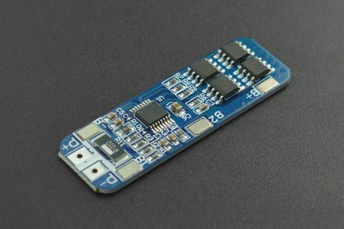
Sounds like it should all be OK. With this unit the points marked “B+” and “B-” are self explanatory but “B1” and “B2” could be a bit misleading. I don’t suppose by any chance you could have those reversed could you. That might make for a funny result.
DFRobot web site has a connection diagram.
So I am using that board and definitely have it wired correctly.
I have the balance charger wired to the cels directly, on the same pads as the board.
My balance charger only has the balance leads, not the P+ and P- outputs.
I’ll check the wiring again.
Hi Andrew
My understanding is the P+ and P- is where you connect the 12.6V for charging and the load for using the battery for a power supply.
There is not much detail re this but that is what it looks like on the web site diagrams and that would make some sense if there is low voltage shut down facility incorporated.
Cheers Bob
yes, that is what I assumed, just that I dont have a 12.6v source, but do have a balance charger with the 4 leads, so the B+ and B- and the two in the middle.
Hi Andrew
So you are not using that unit at all is that correct. You can’t have both connected and to use the DFRobot device you need a 12.6V source.
Cheers Bob
I am using that one, but have the balance leads wired in as well.
No, not using both at once.
I’ve just build a second one and have a 12.6v input configured, trying it out now.
And you can get our latest projects and tips straight away by following us on:
![]()
![]()
![]()
![]()
