This breakout board will solve all your multi-rail power-monitoring problems. Instead of struggling with up to 6 multimeters, you can just use the handy…
I have connected the red wire from my LiPo battery through one of the channels on INA3221, and my program is recording voltages around 3.5v.
However a simple voltage monitor connected to the red and black wires at the Solar Power Manager 5V’s battery screw terminals shows 4.05v, and my multimeter between the same screw terminals shows 4.04v.
I am wondering, is this because I have connected the INA3221 to my ESP32 via the boards Qwiic connector with 3v3 signalling and power ?
I think I may have found the problem - it’s because ESPHome doesn’t log everything to its web interface. ESPHome does log a lot more to its uart/USB interface, and so I changed from powering the ESP32 by USB from the Power Manager … to USB from my PC.
So now I suspect the GND is a bit confused …
the PC is supplying 5V and connecting GND via USB to the ESP32;
the ESP32 is connecting GND to the power manager via i2c connection,
and i guess that’s not the same level of GND as at the battery’s connector
Years back i blew up the serial interface card of a borrowed minicomputer by plugging the different power cords into different wall sockets which, (being an old building) were on different fuses.
So long as the ESP is only being powered by one source it will be fine. Looking at the schematic for the board, the High power side of the board is separated from the low side of the board.
Dan I certainly don’t feel that anything has been sorted.
Out of desperation I came up with a theory for why the INA3221 is measuring a different voltage than the multimeter - and I mentioned it here hoping to get some confirmation, or guidance on what else to check.
The schematic only confuses things further.
I understood that I normally we should measure between VCC and GND. Measuring VIN+1 against VIN-1 gives only a tiny reading … which suggests that the configuration diagrams are all wrong, and VIN-1 should actually be connected to the battery’s GND.
More investigation required …
And in the meantime I have been tidying my wiring ready for deployment (using a physically smaller ESP32-S3-zero) … and all my sensors have stopped responding Thinking that I may have killed all my i2s devices (again) I instead found that the S3-zero is not putting out 3v3 any more. And that the 3v3 buck module from aliexpress is actually outputting 9V … thanks Have ordered some more parts from Core and waiting.
How do you have it wired at the moment? Would it be possible to send through a picture of your hardware and a wiring diagram?
(This will be key to figuring out where the issue might lie)
The schematic helps only if you read the datasheet, this photo along with the other resources in the download section helped me understand this part
That will depend on how you have everything connected, as long as GND comes back to this device you ought to be seeing the same reference, though if you have other devices connected (like the solar manager - that could be low-side switching) they could account for the ~1V drop.
Please don’t connect this board like that, the only thing between it will be the current shunt, and will quickly deplete your battery
Hi Donald, Liam
Have just taken notice of this threads I don’t know the exact circumstance.
Donald.
That is correct, you are measuring the very small voltage developed across the very low value shunt resistor. That is how the current through it is calculated.(within the IC).
No No No. As Liam says that will put the shunt directly across the battery with disastrous results. V? - connects to the load positive which puts the shunt in series between the supply and load. That is correct.
If this board is supposed to measure the high side supply voltage I think there is a monumental mistake here. It can measure current by measuring the small voltage across the shunt as a differential input but without a ground connection to the supply there is NO WAY it is possible to measure supply voltage. I have not read any text on this board but looking at the pics and schematic I can see no provision to connect the battery negative to the board at all. If there is none it cannot possibly measure the supply voltage.
So Donald unless you can find a battery (or supply) negative connection you can’t measure the supply voltage. There may be more information in some text description somewhere but I have not looked far so have not found anything.
Cheers Bob
Hi Donald, Liam
Add on to above
Found the data sheet for that OC used on this board.
It would seem that the device can indeed measure Supply voltage.
BUT the supply ground (all supply grounds if more than 1) have to be connected to IC “Ground” which I assume is the point marked “Gnd” on the board. This will be OK . If more than 1 supply all the grounds will be connected which is probably going to happen anyway.
You have not shown this connection and I have not checked but I would not be surprised if there is no mention in any text. I am not going to do a thorough search I will leave that up to you but I don’t believe this function can happen without the ground being connected.
Here is the relevant block diagram so you can see what happens.
I wasn’t going to unless there was overwhelming recommendations to do so.
I initially bought an INA3221 board off aliexpress (which of course has no documentation or support), and found several reports that there is a major fault with the board and it needs to be wired very differently.
So I bought the Adafruit board from Core so that (a) I could be sure of what I am buying, and (b) because of Adafruit’s worked example (which you linked to) - which may or may not apply to any other board.
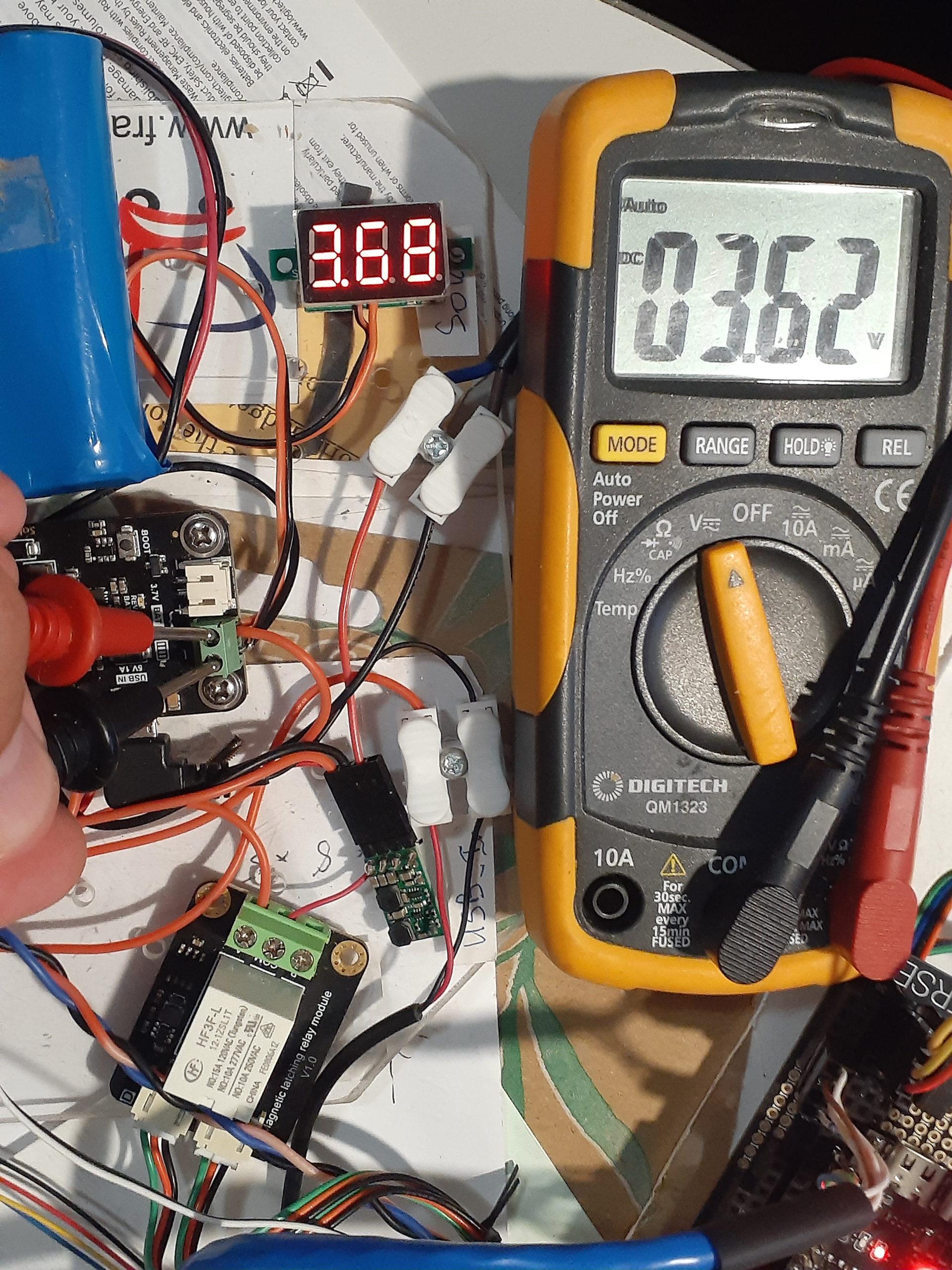
I have been tidying up the wiring ready for deployment … but it does still look rather messy, especially with all the red wires.
The Digital LED Voltmeter and battery are connected to the Power Manager’s Batt IN screw connectors, with the V+ going through the INA3221’s channel 1 (at the left end in this picture). I have double checked that the wiring is matching this segment of the wiring diagram for my power module.
The only connection to the microcontroller is the Stemma QT i2c connection on the INA3221 board. The relays are applied to the Solar panel and USB inputs
The difference between multimeter and Digital LED Voltmeter isn’t too significant - unlike the measurement of 3.42v which INA3221 is reporting to ESPHome.
[18:06:10][D][sensor:093]: 'greenhouse Battery Voltage': Sending state 3.42400 V with 2 decimals of accuracy
[18:06:10][D][main:534]: ### battery is <3.5v (3.42) ###
[18:06:10][D][sensor:093]: 'greenhouse Battery Current': Sending state 0.00440 A with 2 decimals of accuracy
[18:06:10][D][sensor:093]: 'greenhouse Solar Voltage': Sending state 0.25600 V with 2 decimals of accuracy
[18:06:10][D][sensor:093]: 'greenhouse Solar Current': Sending state 0.00000 A with 2 decimals of accuracy
[18:06:10][D][sensor:093]: 'greenhouse USB-in Voltage': Sending state 0.00000 V with 2 decimals of accuracy
[18:06:10][D][sensor:093]: 'greenhouse USB-in Current': Sending state 0.00440 A with 2 decimals of accuracy
As you can appreciate I want my automation to take action when the voltage gets down to 3.3v … but not when the voltage is actually 3.7v
Back again, after all this time of it working correctly, I’m am now having a problem which I think may be a faulty INA3221.
My greenhouse ESP32-S3 is on a cycle of deep_sleep for 30 minutes then 3-5 minutes awake to read a variety of sensors, including Battery Voltage. I expect that the battery will gradually run down during winter (when there is little sunlight for days on end), so I have set the ESP32’s program (in ESPHome) to check for low battery and take evasive action. At <3.4V it sends warning messages to my Home Assistant log, and more strident messages at <3.3v. However below 3.2v the ESP32 should conserve the remaining battery by going into a 3 hour deep_sleep.
I have noticed that the first voltage reading is usually lower than the next couple (as you can see here) but lately the first reading is ridiculouslylow, and triggering the long deep_sleep - even while the Digital Voltmeter is showing value 3.6V
This is my power module. 5V is supplied from the DFRobot Solar Power Manager’s 5V pins to my ESP32-S3. Battery is actually 6600mAh, with voltage measured both by the Digital Voltmeter connected to the same screw terminals as the battery, and INA3221’s channel 3. Since the INA3221 has 3 channels I also record Solar Panel and USB-IN voltages and current … though they really don’t add much useful data. FYI I have found that connecting a Power Bank to the USB-IN is useful in winter to top up the main battery - but having it permanently connected and switching the Latching Relay does not start the Power Bank charging.
It definitely sounds like something is going on with that INA3221.
I know that it’s initial voltage measurement can sometimes be a little low, but it definitely sounds like there’s been a progression with it getting lower and lower.
May I ask what were it’s measurements like before it started having these sudden extreme dips.
The initial voltage measurements have almost always been on the low side … usually by about 0.1V, but occasionally up to 0.35V low. that was OK since the effect was to sometimes trigger the low battery function (go into deep_sleep for 3 hours) a little earlier that I really intended.
In the short term the answer is probably for me to ignore the first reading after power-on, and hope the INA3221 doesn’t deteriorate further. So far so good.
UPDATE: Even ignoring the first readings, overnight it has reported a lot of low readings <3v3, despite the Digital Voltmeter still showing 3v56 - so not good
This is my second INA3221 - I bought this one from Core because of all the comments that anything from Ali is rubbish, and that the one from Ali suddenly started reporting LiPo Battery Voltage of 28.97V !
So … now I’m wondering if it might be my amateur soldering, that 1 channel is faulty, or the whole INS3221 chip. Could a bad solder of the screw terminal into the INS3221 board give these results ?
Thinking that while I have the greenhouse on my work desk, maybe I should do a little experimenting … such as connecting the Li-Po battery leads to several measuring devices simultaneously and compare them. Maybe to multiple INA3221 channels, and/or another INA3221, and/or DFRobot Digital Wattmeter (SEN0291), and/or MAX17048 ? Would it be feasible to set up several of these in parallel, or is my thinking too simplistic ?
I have changed my programming to record all battery voltage readings - but to ignore the first after waking, and take action based on the average of the other 3 readings.
And of course I have just noticed that that channel on the INA3221 has been recording zero Battery Current for several days. Looks like my chip is dud
Now I have to revisit my power module and do more soldering knowing that it may be something I have done to break this INA3221 and the last one … and probably the next one.
Damn. Sorry to hear that, @Donald23173. It may feel like failure, but at least you’re narrowing down possible causes with each pass through.
Maybe write down some detailed notes while you’re soldering the INA3221 and setting it back in the circuit every step of the way. Coming back to it, it might tell you something that you’ve missed.