Hi All
This post is rather lengthy so bear with me.
Firstly this post is not meant to be critical of Arduino. It is still and has been an excellent product and does what it has been designed for very well. BUT if some boundaries are exceeded like what I have been experimenting with it will fall a bit short.
The following is meant to help those who may have been experiencing some unexplained or funny results, and those who may be considering trying a bit much. All devices, no matter how good, have some limitations and it does more good than harm to be aware of them. Makes life much easier.
All started out with an idea for a pulse generator with separate control of period thus frequency and pulse width thus duty cycle. Displaying these 4 parameters on a suitable device.
The idea here is to have a unit suitable for testing various small motors:
50% duty cycle and variable frequency to provide a pulse train for stepper driver board.
Set frequency and variable duty cycle for brushed motor speed control.
50Hz (20mSec period) and variable pulse width for servo motor control.
Sounds easy ???
Using Pots or Rotary Encoders it is not difficult to generate the numbers for Period, Frequency, Pulse Width and Duty Cycle and display these. Also the numbers (microseconds) for pulse HIGH and pulse LOW.
Generating these pulses is another matter. I don’t think it can be done with 1 device. The processing and displaying time, which can be significant, is effectively added to the OFF time with impossible results so 2 devices are needed. One to generate the numbers and display and the other dedicated to generate the pulse stream. Or a device capable of true multitasking. I have yet to work out how best to do this. I have provisionally looked at the dual core Pico but I think you have only one memory position accessible to both cores, I need 2.
I might have to go to plan B. Still work in progress.
Back to the subject of this topic.
Using Arduino UNO Ver 3 (Freetronics Eleven) which I am more familiar with.
Oscilloscope. Atten ADS1022C. Calibration status unknown. Checks OK against Function Generator and internal calibrator.
Function Generator. UNI-T UTG932E. New.
While experimenting I discovered that the “digitalWrite” command seems to add more than 4µSec to everything. This means that a 10µSec pulse effectively becomes over 14µSec. At 1kHz and 50% duty cycle this is more than 0.8% and gets worse as the frequency gets higher as the 4+µSec is constant. Not good. This time seems to change as well causing a “jitter” as observed on oscilloscope. Have not been able to get to the bottom of this “jitter” yet. A bit hard to pin down as it appears to be completely random and not cyclic so difficult to catch. It could even possibly the timers (micros() and millis() running out and wrapping to start again. I am not sure how often this happens.
This 4 point something µSec addition is pretty simply described in an article here.
And concerns some housekeeping carried out by “digitalWrite” before applying the command. The author describes a method to bypass this housekeeping which reduces this 4+µSec to 124nSec which could be ignored for most practical purposes.
The thing I would not agree with here is that the author has attempted to measure this 4µSec by averaging 1000 readings using the timers in the device he is measuring. He came up with a figure of a bit over 3µSec. I prefer to use another instrument which I have demonstrated as he later states the internal timers have a resolution of 4µSec which I haven’t been able to verify yes or no.
Now to my measurements.
Pic 1 is just my very untidy workspace. Working real estate is almost non existent these days

Following is a short sketch to measure the delays due to “digitalWrite”.
void setup() {
   // put your setup code here, to run once:
  pinMode(6, OUTPUT);
  pinMode(5, OUTPUT);
}

void loop() {
  // put your main code here, to run repeatedly:
  digitalWrite(6, HIGH);
  delayMicroseconds(50);
  digitalWrite(6, LOW);

  digitalWrite(5, HIGH);
  digitalWrite(5, LOW);
  digitalWrite(5, HIGH);
  digitalWrite(5, LOW);
}
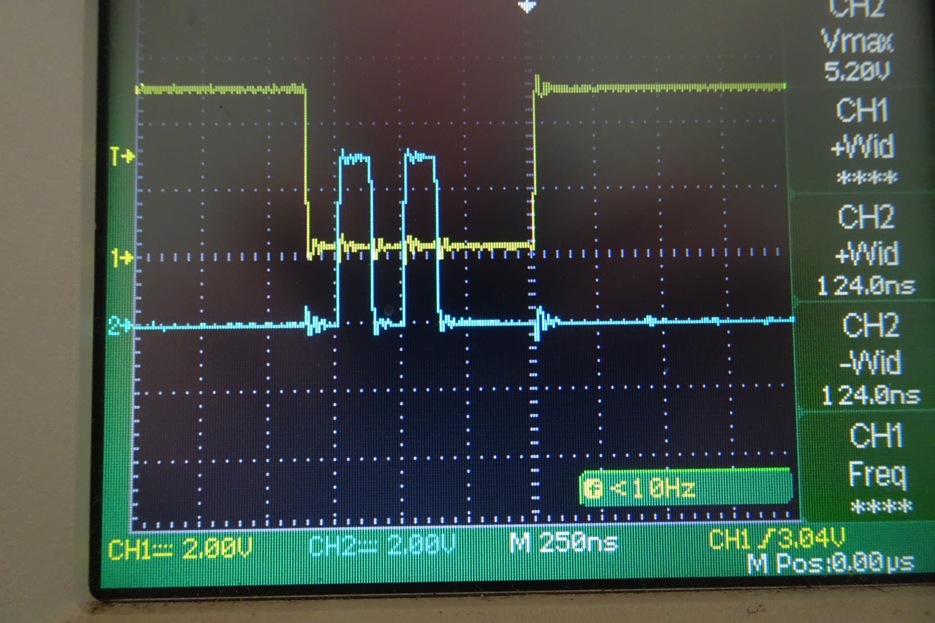
The sketch generates a 50µSec pulse on pin 6 to indicate start of loop. In each of the following cases this is monitored by oscilloscope Ch 1 (yellow trace) and triggered Ch 1. 2 pulses are generated on pin5 with no delays so the only delay will be due to “digitalWrite”. Monitored on Ch 2 (blue trace).
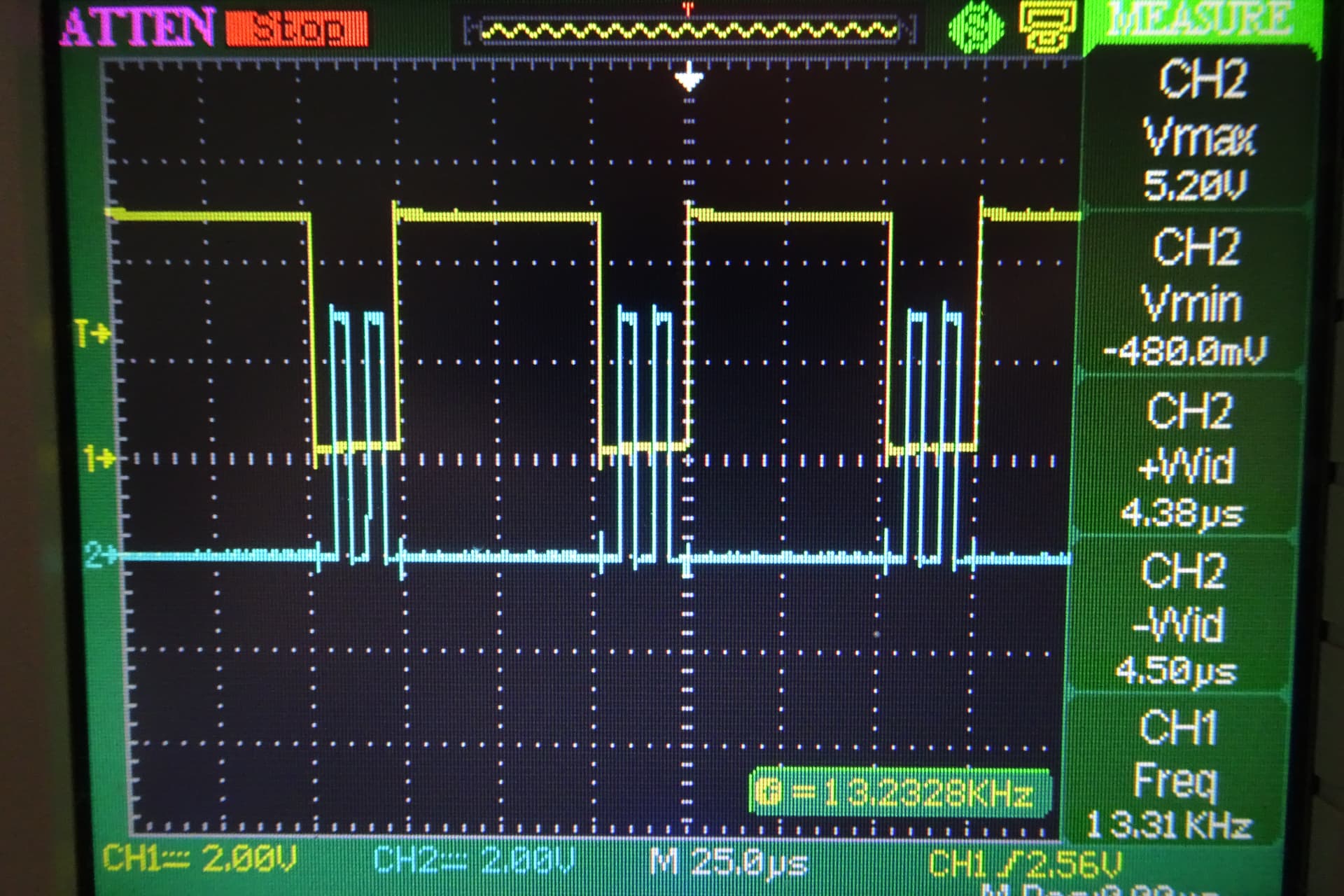
The delays of 4.38µSec and 4.5µSec can be clearly seen and close inspection shows Pin 6 is slighter greater than 50µSec.
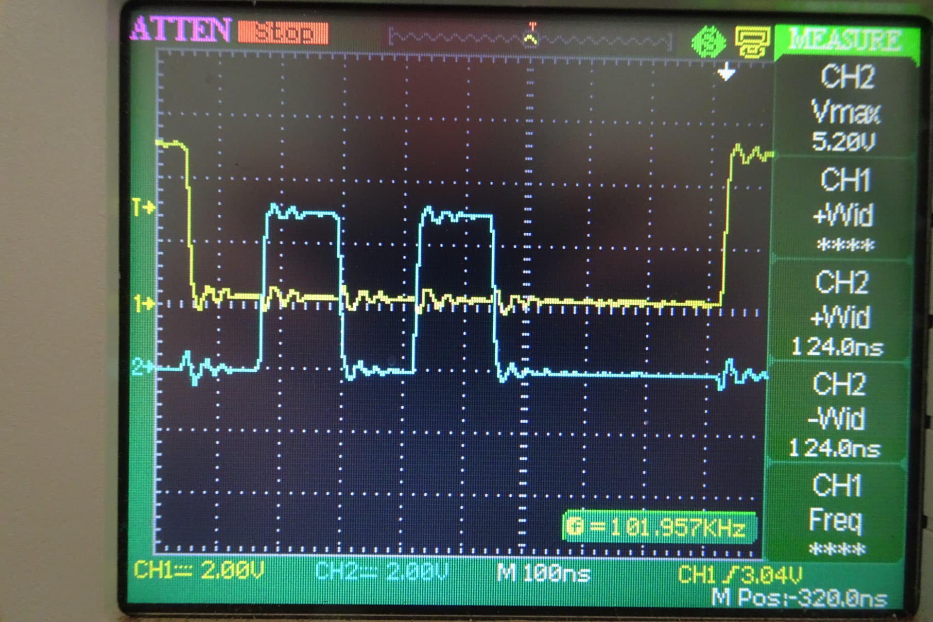
Next Pic is expansion of last where the delays may be clearer
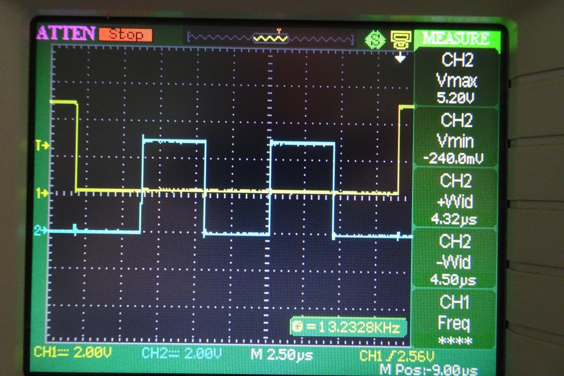
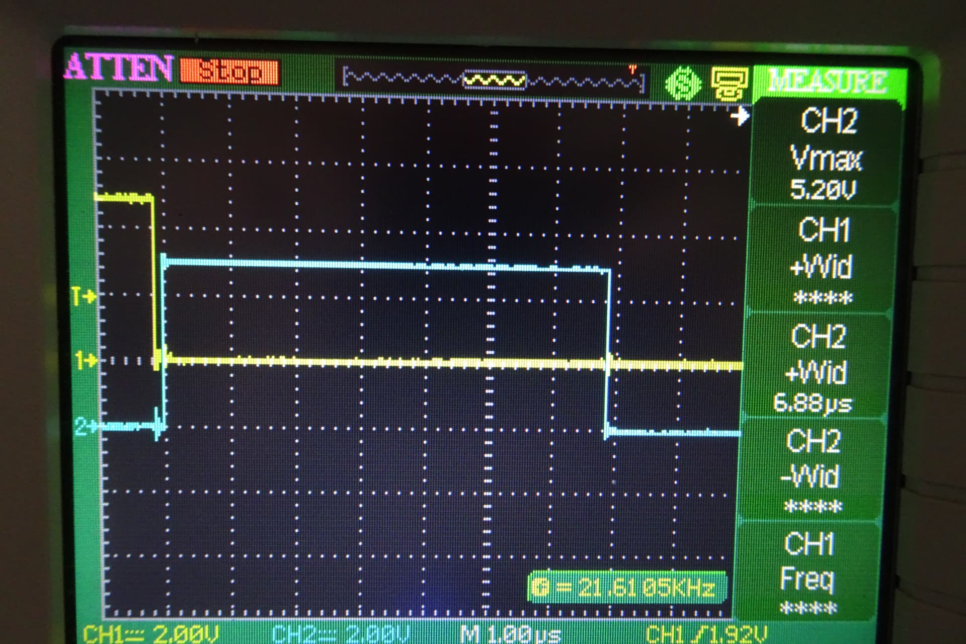
Next Pic. Further expansion shows the delay between the last pulse on Pin 5 and the start of loop pulse on Pin 6. Most of this delay will be the 4.38µSec delay for the “digitalWrite” on Pin 6 plus a little bit to start the next loop.
Next uploaded the following sketch which replaces the “digitalWrite” with the direct pin manipulation as described in the linked article above. Note Pin changes to get pins both on Port B.
void setup() {
  // put your setup code here, to run once:
  pinMode(8, OUTPUT);
  pinMode(9, OUTPUT);

}

void loop() {
  // put your main code here, to run repeatedly:
  PORTB = PORTB | B00000001;
  delayMicroseconds(10);
  PORTB = PORTB & B11111110;
  PORTB = PORTB | B00000010;
  PORTB = PORTB & B11111101;
  PORTB = PORTB | B00000010;
  PORTB = PORTB & B11111101;

}
As you can see I have removed all the delays except the start of loop indicator pulse (10µSec)
Result in next Pic, much faster.
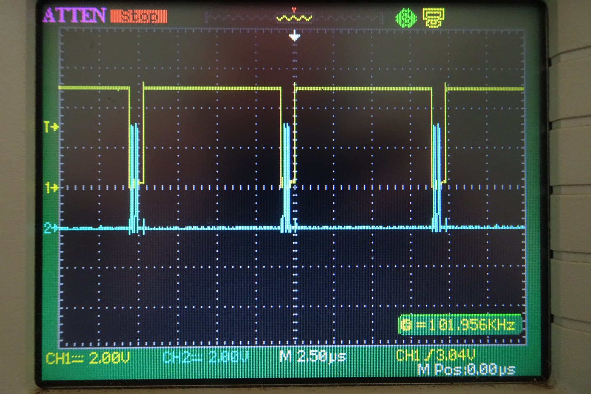
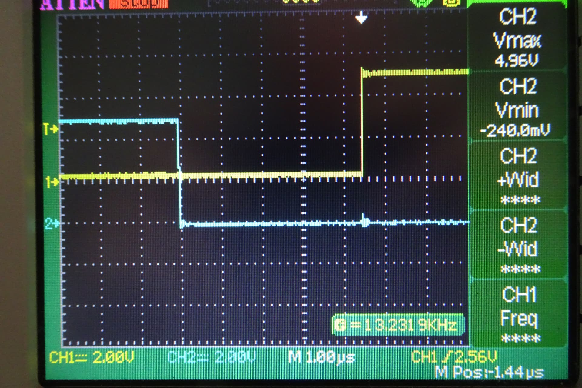
Next Pic is the expanded view of the relevant pulses. The delay is now 124nSec. The clock period of 16MHz is 62.5nSec so this looks suspiciously like 2 clock pulses to execute this command which is what you would expect.
Next Pic is a further expansion of the same.
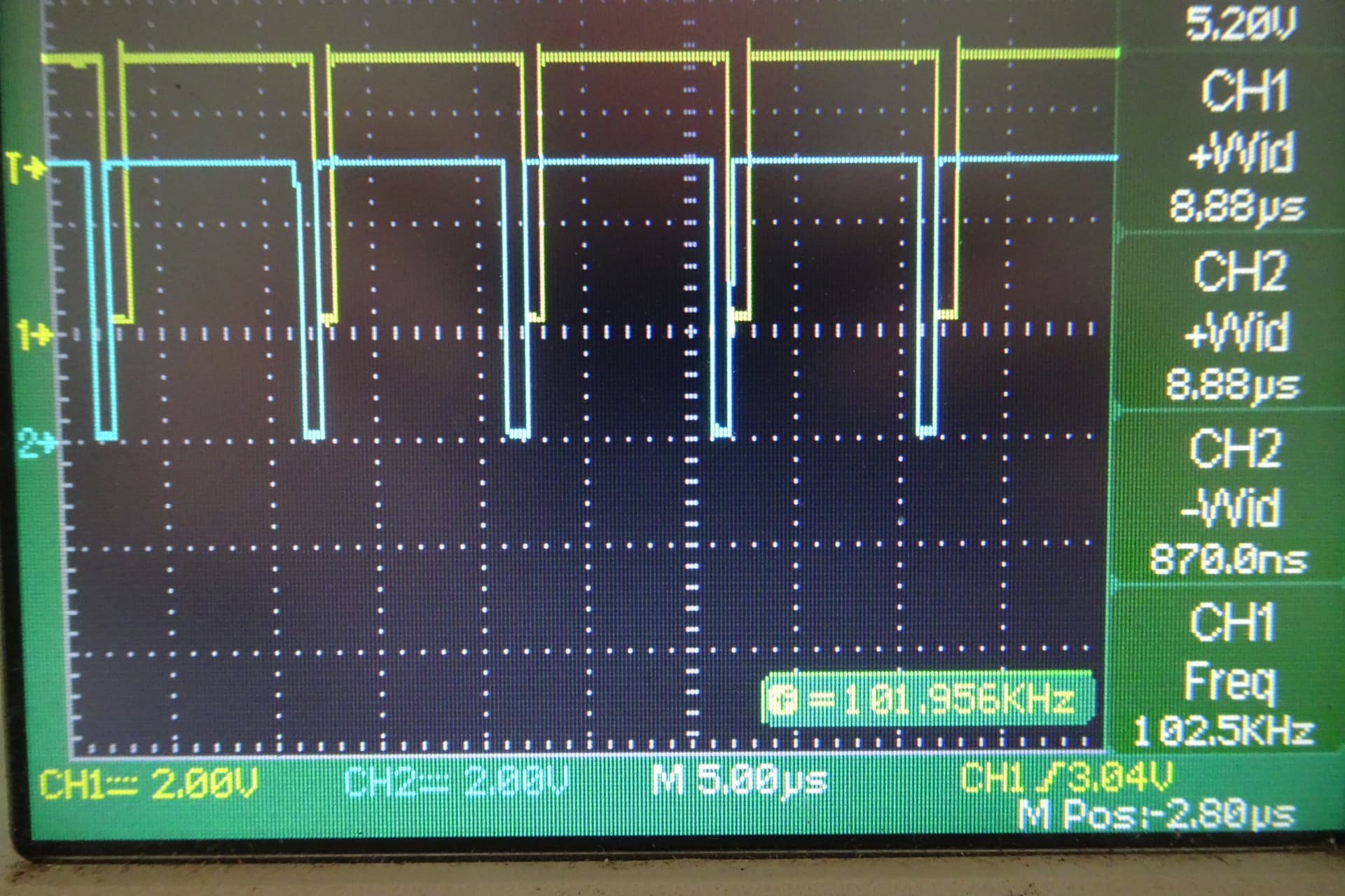
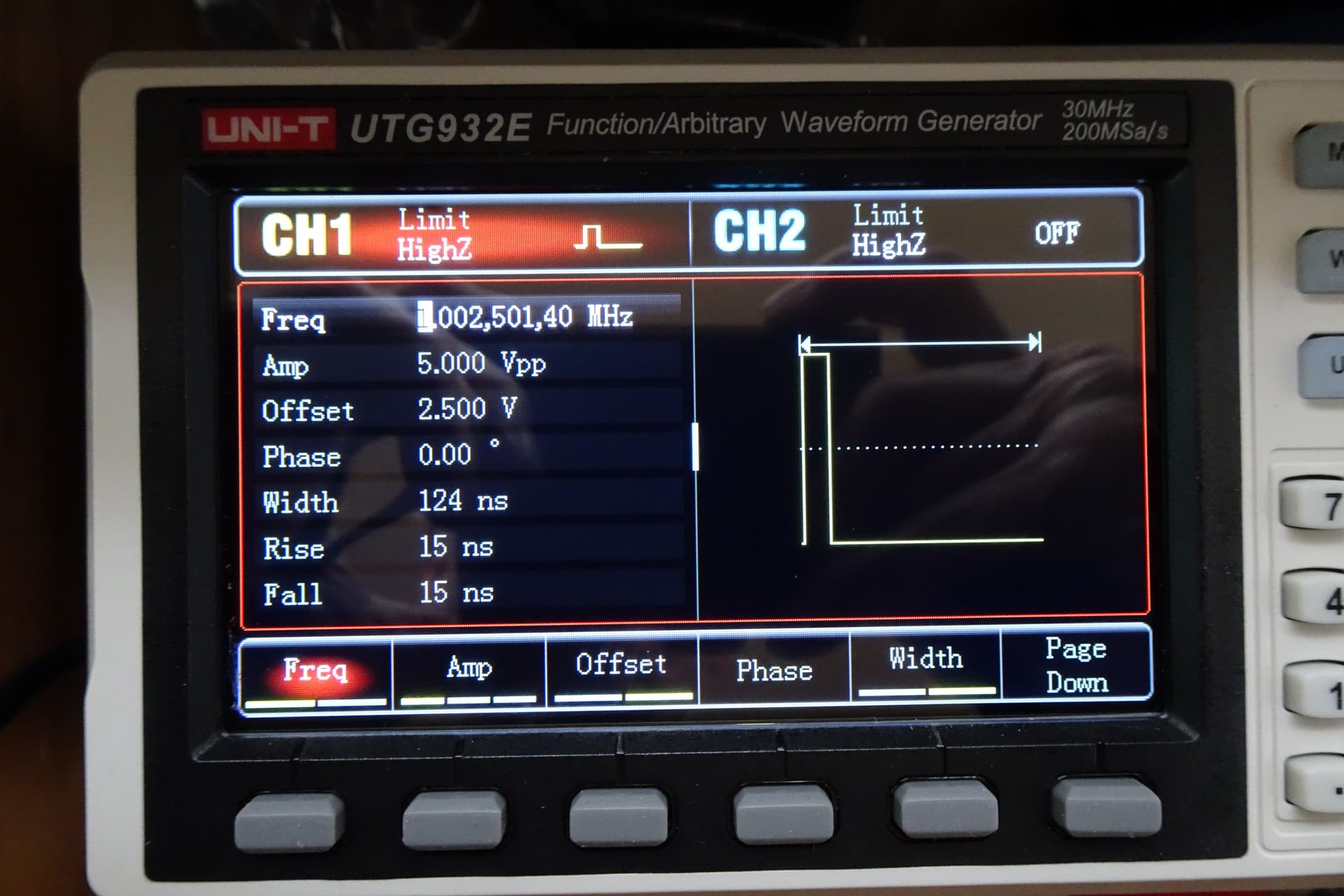
The next Pic is an attempt to confirm the scope measurements. The best comparison I have available (except for the built in calibrator which is spot on at 1kHz) is a 2 week old Uni-T function generator. I connected to scope Ch 2 leaving Ch 1 on the Arduino start of loop pulse. As you can see I got very close and by adjusting the function generator to the same 8.88µSec and the FG frequency to get an almost stationary trace the results almost spot on. Ch 1 says 8.88µSec, Ch 2 says 8.88µSec and FG says 8.88µSec. And frequency Ch 1 says 102.5kHz and FG says 102.5014kHz. I had trouble getting a stationary blue trace probably due to the small difference.
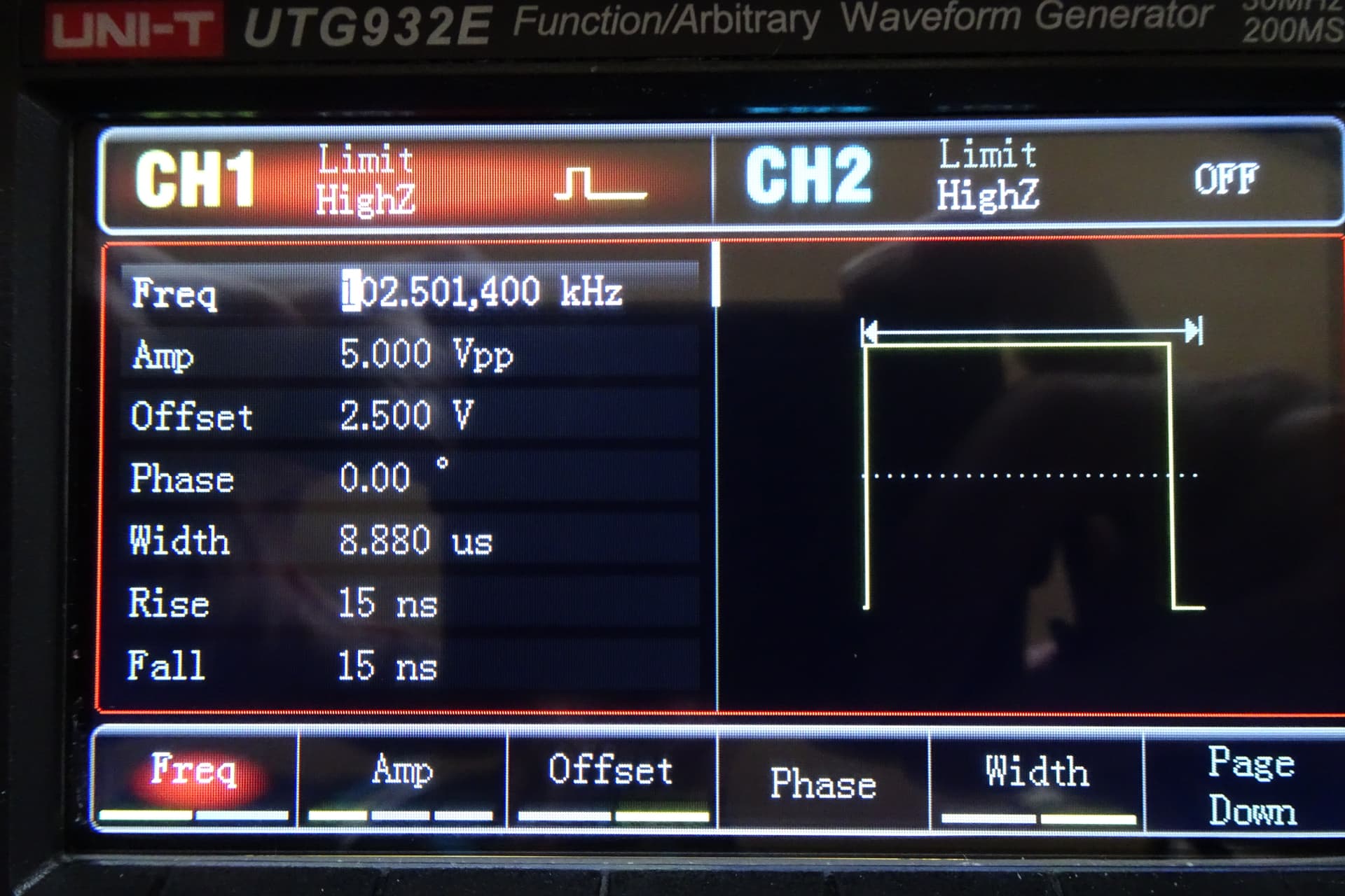
Pic of Function generator screen.
The next Pic I re established the pulses and connected Ch 1 to the Function Generator outputting a pulse of 124nSec, triggering off Ch 2. As you can see the scope measures 124nSec on both Ch 1 and Ch 2 so from here on I will believe the scope.

Next a Pic of the FG screen for verification.
During this I had noticed that now with the “fast” digitalWrite the pulses are not long enough. The loop start indicator is now 8.88µSec instead of the requested 10µSec. I had previously noted the 16MHz clock speed measured 16.13MHz (on scope) and I put that down to possible probe interference. BUT the period for 16.13MHz works out at 62nSecwhich would explain the 124nSec delay measurements. If this were the cause of this error it would appear as a percentage, not a consistent 1.12µSec across the board.
I thought this might have something to do with the stated (but unverified) resolution of 4µSec in the timers so I loaded another sketch with a 10µSec start indicator, a pulse of 8µSec, a delay of 20µSec and another pulse of 12µSec. The 2 pulses having a direct relationship with 4µSec.
void setup() {
  // put your setup code here, to run once:
  pinMode(8, OUTPUT);
  pinMode(9, OUTPUT);

}

void loop() {
  // put your main code here, to run repeatedly:
  PORTB = PORTB | B00000001;
  delayMicroseconds(10);
  PORTB = PORTB & B11111110;
  PORTB = PORTB | B00000010;
  delayMicroseconds(8);
  PORTB = PORTB & B11111101;
  delayMicroseconds(20);
  PORTB = PORTB | B00000010;
  delayMicroseconds(12);
  PORTB = PORTB & B11111101;

}
Next Pic. Overall result. Note Ch 1 8.87µSec instead of 10µSec.

Next Pic. Expanded first pulse. 6.88µSec instead of 8µSec .
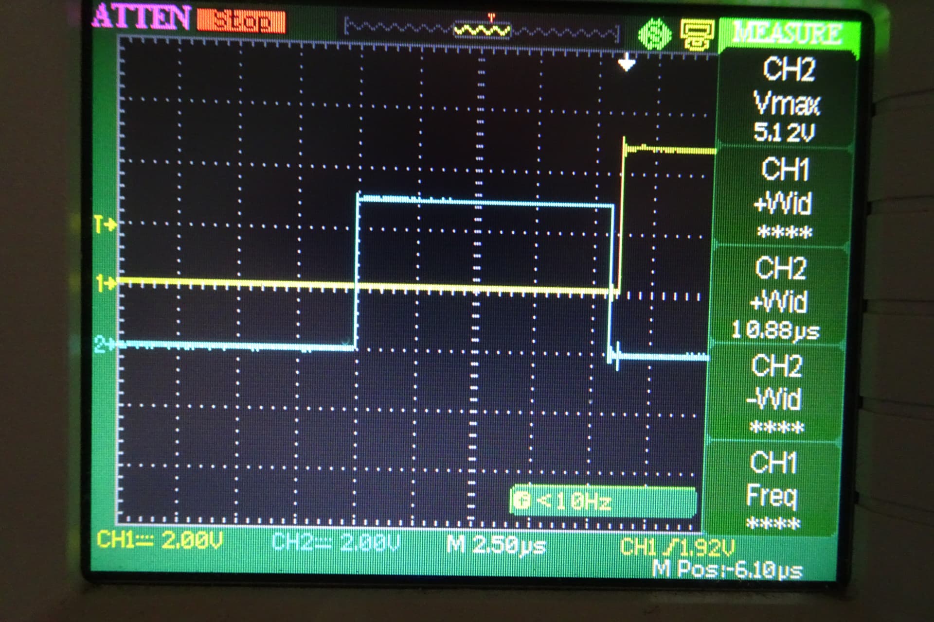
Next Pic. Expanded second pulse. 10.88µSec instead of 12µSec.
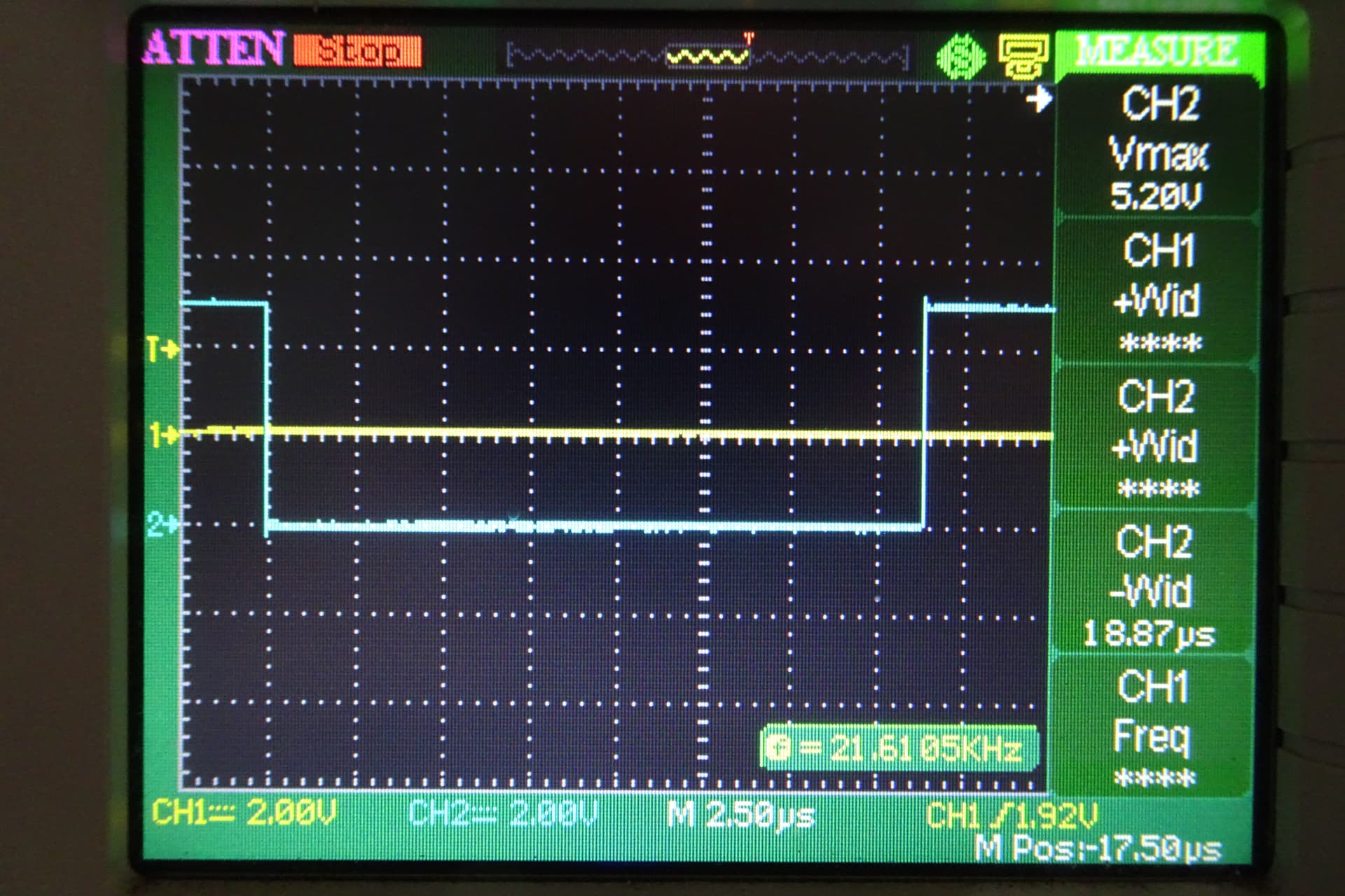
Next Pic. Expanded delay between pulses. 18.87µSec instead of 20µSec.
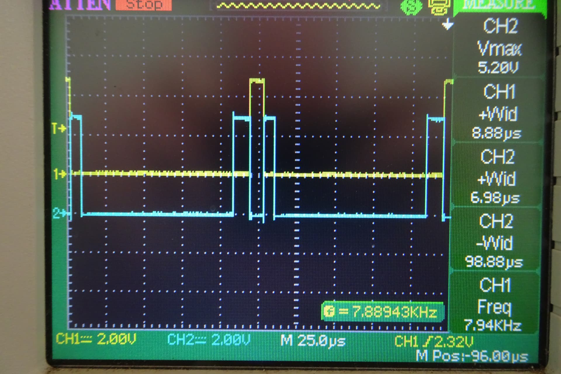
Just to prove this error os not a percentage I increased the delay between pulses to 100µSec.
Next Pic the result. 98.88µSec.
I realise this is a very very long post for which I apologise but I could not think of a way of making it any shorter. I think the pictures while taking up much space shorten up any explanatory text by much more.
I hope this might explain some past little errors and prevent future hair pulling.
I have yet to track down the so called 4µSec resolution of the timers, maybe some of the Arduino Gurus could help here.
Also the missing 1.12µSec in pulse width when using the “fast” digitalWrite could do with some explanation.
have a NanoEvery available so I might quickly repeat some of this in case there is any difference between models with the same processor. I don’t really expect any.
Thanks for your patience.
Cheers Bob