**this is how I connected my ASD1115 and FSR to the breadboard then to the rasspery pi using T-coppler adafruit but I still got endless errors after endless tries that I2C bus is not found althoug I connected it , what might be wrong?

1 Like
Hey there, @Abdulrahman309112, and welcome to the forum. Glad to have you here.
The wiring looks like it should be correct there. Can I confirm that you have enabled I2C in the Raspberry Pi’s settings?
In addition, could you please upload the code that you’re currently using so I can see what might be going wrong.
Yes I enabled I2C and I used two codes for trying out, one from the tutorial from your website:
#import all necessary functionality to the Script
import time
import Adafruit_ADS1x15

# Create an ADS1015 ADC (16-bit) instance. Note you can change the I2C address from its default (0x48) and/or bus number
adc = Adafruit_ADS1x15.ADS1015(address=0x48, busnum=1)
# Choose a gain of 1 for reading voltages from 0 to 4.09V.
GAIN = 1
#Create a Loop that repeats forever
while True:
    #Read the value coming from Analogue In Pin 0, set gain to the above value
    values = adc.read_adc(0, gain=GAIN)
    #Print the values to the shell, right click shell to enable the plotter
    print(values)
    #pause for just a tiny fraction of a second (so as not to be overwhelmed by data)
    time.sleep(0.1)
And from the asd ebook:
import time
import Adafruit_ADS1x15
adc = Adafruit_ADS1X15.ADS1115() # Create an ADS1115 ADC (16-bit) instance
GAIN = 1
print( ‘[press ctrl+c to end the script]’)
try: # Main program loop
while True:
values = adc.read_adc(0, gain=GAIN) # Read the ADC channel o value
print (’ {0:>6}'. format (values))
time.sleep (0.5)
# Scavenging work after the end of the program
except KeyboardInterrupt:
print( ‘Script end!’)
Each with its packages installed
Thanks for that, Abdul,
Ok, its good to know that you have enabled the i2c on the Raspberry Pi. Now, I want to confirm whether this is a code related issue or a wiring related issue.
From a bash shell, can you please use the following commands:
sudo apt-get install i2c-tools
i2cdetect - y 1
The i2cdetect command will let us see if the Pi can detect the Adafruit board on bus 1.
If it can, we will know that this is definitely a coding issue. If we can’t, that points to wiring being a fault.
Please let me know the results.
Hello Jane, thank u so much for quick reply.
I already made this test and it didn’t detect any bus. And as I understand it should detect 48 num.
So I can say it’s hardware issue but not sure really how to trace it.
also to ask what bus 1 mean, does it mean specifically A0 as I applied on A0 and A1 with code?
Should the packages be affecting or related to that bus is not detected?
One last thing could ADDR be the reason somehow?
I will attach a pic from the errors I got after run on Thonny IDE.
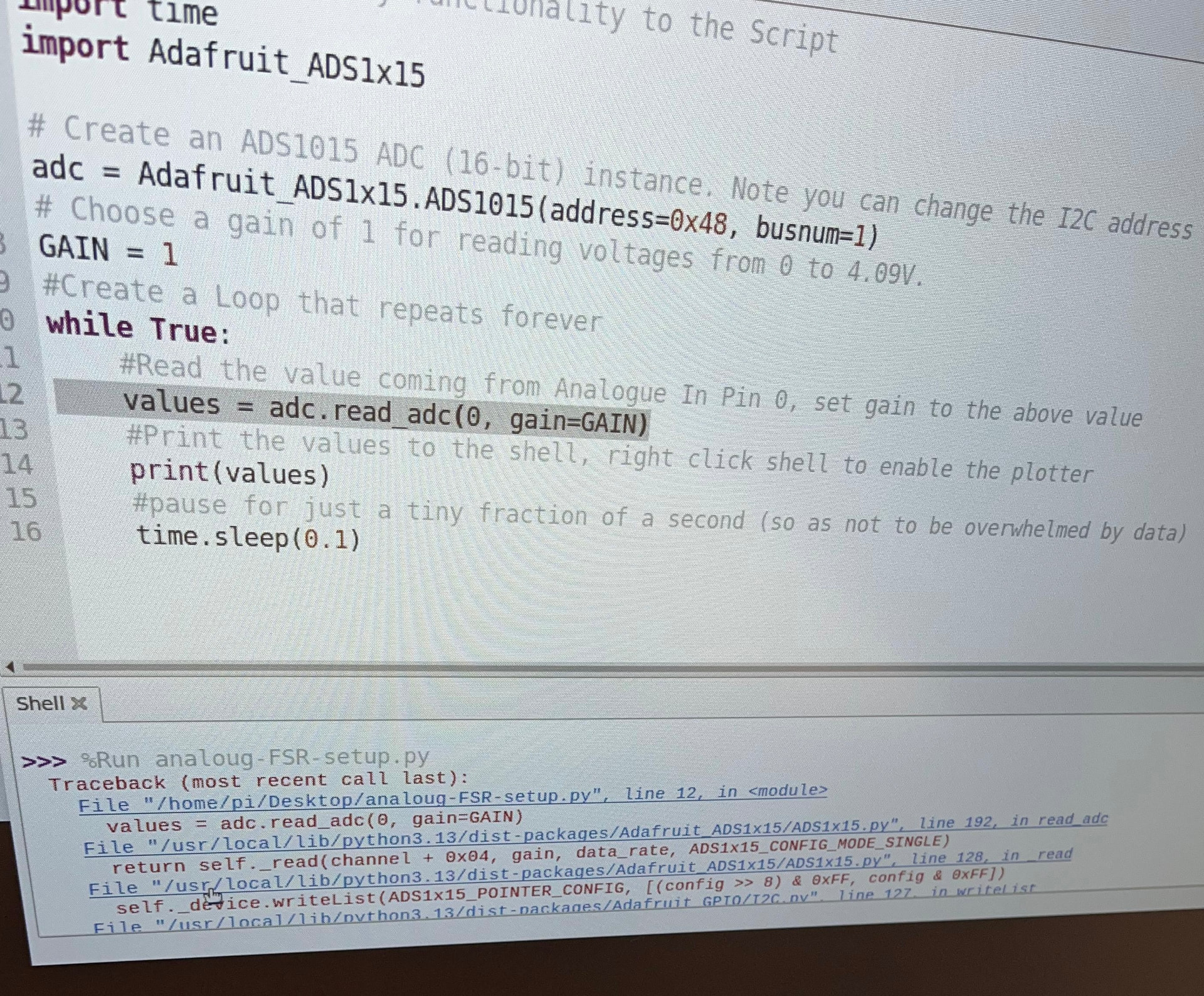
You have an ADS1115 (16-bit), but your code creates an ADS1015 (12-bit).
this is the problem line
adc = Adafruit_ADS1x15.ADS1015(address=0x48, busnum=1)
it should be
adc = Adafruit_ADS1x15.ADS1115(address=0x48, busnum=1)
If you get endless I2C bus not found errors, wiring alone is rarely the cause. First, ensure I2C is enabled in raspi-config and reboot. Check that /dev/i2c-1 exists after reboot. Always scan bus 1, not bus 0. Use sudo i2cdetect -y 1 only. Verify SDA is GPIO2 and SCL is GPIO3. These are pins 3 and 5. Many T-Cobbler boards cause pin confusion. Confirm ADS1115 is powered from 3.3 V only. Never use 5 V on Raspberry Pi I2C. Tie the ADDR pin to ground initially. Disconnect the FSR during debugging. Miswired sensors can lock the bus. Keep SDA and SCL wires short. Avoid long breadboard jumpers. Check that i2c_bcm2835 and i2c_dev are loaded. For a proven reference design, you can see here: https://www.pcbway.com/project/shareproject/16_Ch_ADC_16_Bit_on_One_I2C_Bus_a65708b5.html.
So I will try without the T-coppler for once, but isn’t the ADS1115 valid for 5 v power and if I used in 5 V could it be the case the pi I2C is damaged?
And u want me to use the FSR while debugging the code? And for
Check that i2c_bcm2835 and i2c_dev are loaded
Do u mean as packages?
Sorry *not to use the FSR while debugging but what then should A0 pin on the ADS be wired to?
I think in the video he destroyed the ADS 4.7 k resistor, is that something I should consider?
It actually has nothing to do with the A0 or A1, as they are simply the pins for the AC input on the breakout. The i2c buses are the communication channels between the Pi and the breakout. The Pi typically has two of them and based on your wiring you should be connected to the first.
So the ADS1115 you’re using is valid for between 2V to 5V so the Pi’s i2c ports should be fine as long as you switch the power from 5V to 3.3V.
But I am curious if you’re getting the same problems without the T-Coupler as you are with it.
I’m not sure what video you’re referring to, but I probably wouldn’t unless you have a clear idea of what it does.