Project by James46717; Smart Watering System

I’ve just shared a new project: “Smart Watering System”


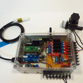
This began as an idea after building a very basic single-channel unit. Commercial smart watering systems use a Wifi connection to the internet and get weather reports to determine the level of watering required. These systems are set up and controlled via a phone or tablet app, often you have to register with the company.

I wanted a stand-alone device based on the Raspberry Pi Pico using sensors to determine the watering required. With no need for external internet access.

Read more on the project write-up.

8 Likes

Hey Jim,

Sorry I didnt reply earlier, this is a super sick project and has inspired me to try a hand at a gardening-electronic project.

Sick write-up as usual, the way you cram everything into the enclosure so neatly is something else!
Love the OLED + nRF custom Python library :smiley:

1 Like

Is there any video of this project?

Hi,
very nice project.

I am looking seriously at building and looking to make sure I understand as much as possible before jumping in, hence the question:

What LCD’s are supported for the Pi4 programmer?
I can see reference in the code “Display in GUI full screen, configured for 640x480 window”.
But cannot see any reference to what model LCD’s supported or a any discussion on adapting code for different LCD hardware.

Any tips?

The LCD attached to the Pi 4 is for portability so it can be battery powered.
During development the HDMI from the Pi 4 was connected to a normal PC LCD monitor.
The Pi 4 OS switches to the HDMI if a monitor is connected.
The tkinter Library is used to produce a GUI.

# window setup
display=tk.Tk()
display.title('Smart Watering System')
display.attributes('-fullscreen', True)
display['bg']="#777777"

When -fullscreen was set to True the LCD viewable area was 640x480, so that was used to place objects on the screen. Most of this was trial and error, seeing what resulted and worked best. First time using tkinter and probably could be done better, but I achieved the results I wanted.
Not using full screen made it hard to read on the LCD, considering it could be outside in varying light conditions.

Different LCD’s may display differently.
But considering the power of the Pi 4 OS, the tkinter library, and no need to define the type of LCD; I think others should work. Maybe not a 3.5" GPIO display but others that connect to the video bus of the Pi 4.

This project was a proof of concept. Was it possible for a Pico to be used as a smart controller ??
Could the TX/RX devices work with a Pico and a Pi 4 ??

Anyway, thanks for your post.
Cheers
Jim

EDIT: Been a while since I visited this project. Just looked at the pics and note one shows the screen as a window on the LCD. Maybe that was before I used -fullscreen True, unsure. Might have to do some checking. Have run it as a bench test only, and it has been off since it run ok for over a month.

1 Like

No video, sorry.
Project was a proof of concept.
It answered a few questions I had and has not gone any further.
I put it here to show what can be done with a RPi Pico, PiicoDev products and the TX/RX devices.
I wanted to avoid using WiFi or Bluetooth so the Radio link devices were perfect.
Makes the whole thing standalone.

Cheers
Jim

1 Like

Did some checking.
The screen is a Pi Foundation 7" touch screen with a resolution of 800x480 housed in a SmartPi Touch 2 stand.

So in my opinion any LCD screen with a resolution of at least 800x480 should work.
But, the software only uses 640x480 for displaying objects, so a screen with 640x480 should also work.

Note:
The Pi 4 has two HDMI ports. The one next to the power cable switches correctly when using a HDMI monitor. The other one does not.

Regards
Jim

@James46717 Hi James, thank you for uploading such a cool project! I felt compelled to start a similar project that also utilizes 2x nRF905, Rasp pi 4 and a pico. But I am currently stuck on the most basic of tasks; getting the two devices to talk to each other…
Your nRF905 driver worked for the raspberry pi 4. I assume it works because the config got applied,
nRF905 = 0x6c 0xc 0x44 0x20 0x20 0x55 0xaa 0x55 0xaa 0x18, furthermore the register commands of reading and writing addresses work (printing the first few bytes actually gave back something other than 00s).
However, the problem lays on the rasp pico. The config does not get applied nRF905 = 0x00 0x00 0x00 0x00 0x00 0x00 0x00 0x00 0x00 0x00 and the register commands does not reach because whenever I do spi.read(10) after writing to it, it always return 00s. I attached the code below (which is your code minus the humidity date check etc).
I think those are the reasons why the fault is on pico’s side? I doubled, and tripled check the pins ensuring they are correctly placed. I hope that you could provide me with some pointers as to where did I not apply your work correctly, thanks a ton! :pray:
One more thing I would also like to note is that the Address Match and Data Ready checks at the main loop always run true, even when I’m not running the Rasp 4’s nRF905…

import time
from machine import SPI, Pin

############################## nRF905 func lib
############### Radio TX RX
def read_cfg_reg(spi, cs):
    cs.value(0)
    spi.write(b"\x10")
    data = bytearray(spi.read(10))
    print(f'data1: {data}')       # all zeros?
    cs.value(1)
    return data
    
def write_cfg_reg(spi, cs, data):
    cs.value(0)
    spi.write(data)
    cs.value(1)
    return
    
def read_TX_address(spi, cs):
    cs.value(0)
    spi.write(b"\x23")
    data = bytearray(spi.read(4))
    cs.value(1)
    return data

def write_TX_address(spi, cs, data):
    cs.value(0)
    spi.write(b"\x22")
    spi.write(data)
    cs.value(1)
    return

def read_TX_payload(spi, cs, size):
    cs.value(0)
    spi.write(b"\x21")
    data = bytearray(spi.read(size))
    cs.value(1)
    return data

def write_TX_payload(spi, cs, data):
    cs.value(0)
    spi.write(b"\x20")
    spi.write(data)
    cs.value(1)
    return

def read_RX_payload(spi, cs, size):
    cs.value(0)
    spi.write(b"\x24")
    data = bytearray(spi.read(size))
    cs.value(1)
    return data
    
############### nRf905 config
def print_Config_Reg(msg,Config_Reg):
    print(msg,hex(Config_Reg[0]), hex(Config_Reg[1]), hex(Config_Reg[2]), hex(Config_Reg[3]), hex(Config_Reg[4]), hex(Config_Reg[5]),
          hex(Config_Reg[6]), hex(Config_Reg[7]), hex(Config_Reg[8]), hex(Config_Reg[9]))
    return

def set_cfg_register(spi,cs,cfg):
    Config_Reg = bytearray((0,0,0,0,0,0,0,0,0,0))
    print(f'cfg_reg1: {Config_Reg}')
    Config_Reg = read_cfg_reg(spi, cs)
    print(f'cfg_reg2: {Config_Reg}')

    Config_Reg[0] =  cfg['CH_NO']
    Config_Reg[1] =  cfg['AUTO_RETRAN'] << 5 | cfg['RX_RED_PWR'] << 4 | cfg['PA_PWR'] << 2 | cfg['HFREQ_PLL'] << 1 | cfg['CH_NO_MSB']
    Config_Reg[2] =  cfg['TX_AFW'] << 4 | cfg['RX_AFW']
    Config_Reg[3] =  cfg['TX_PW']
    Config_Reg[4] =  cfg['RX_PW']
    Config_Reg[5] =  cfg['RX_Address0']
    Config_Reg[6] =  cfg['RX_Address1']
    Config_Reg[7] =  cfg['RX_Address2']
    Config_Reg[8] =  cfg['RX_Address3']
    Config_Reg[9] =  cfg['CRC_MODE'] << 7 | cfg['CRC_EN'] << 6 | cfg['XOF'] << 3 | cfg['UP_CLK_EN'] << 2 | cfg['UP_CLK_FREQ']

    write_cfg_reg(spi, cs, Config_Reg)
    Config_Reg = read_cfg_reg(spi, cs)
    print_Config_Reg("nRF905 Config =",Config_Reg)
    return

##############################  GPIO PINS
LED = Pin(25, Pin.OUT)

TXEN = Pin(11, Pin.OUT)
PWR = Pin(12, Pin.OUT)
CE = Pin(13, Pin.OUT)
DR = Pin(14, Pin.IN, Pin.PULL_UP)
AM = Pin(15, Pin.IN, Pin.PULL_UP)
CSN = Pin(17, Pin.OUT)

############### GPIO STATE SETUP
LED.value(1)
PWR.value(1)
CE.value(0) # disable radio
TXEN.value(0) # RX
CSN.value(1) # disable comms

############### nRF905 Config Var
spi = SPI(0, baudrate=1000000, polarity=0, phase=0, bits=8,
    firstbit=SPI.MSB, sck=Pin(18), mosi=Pin(19), miso=Pin(16))

# TX_Ad of pico is RX of rasp 4
TX_Address = bytearray((0x55,0xAA,0x55,0xAA), 'UTF-8')
RX_Address = bytearray((0xAA,0x55,0xAA,0x55), 'UTF-8')
bufsize = 32
nRF905_Config = {'AUTO_RETRAN':0, 'RX_RED_PWR':0, 'PA_PWR':3, 'HFREQ_PLL':0, 'CH_NO_MSB':0,
                 'CH_NO':0x6C,
                 'TX_AFW':4,'RX_AFW':4,
                 'TX_PW':bufsize,
                 'RX_PW':bufsize,
                 'RX_Address0':RX_Address[0],
                 'RX_Address1':RX_Address[1],
                 'RX_Address2':RX_Address[2],
                 'RX_Address3':RX_Address[3],
                 'CRC_MODE':0, 'CRC_EN':0, 'XOF':3, 'UP_CLK_EN':0, 'UP_CLK_FREQ':0}

############### TX message
def print_b_arr(x):
    s = ""
    for i in x:
        s += chr(i)
    # print(s)
    return
    
def TX_Message(address, payload):
    TXEN.value(0)
    CE.value(0)
    # checks for valid len of 32, pad with space if not
    if len(payload) < 32:
        for i in range(len(payload), 32):
            payload += ' '
    else:
        if len(payload) > 32:
            payload = payload[0:32]
    write_TX_address(spi, CSN, address)
    write_TX_payload(spi, CSN, address)
    TXEN.value(1)
    CE.value(1)
    # confirm delivery
    while not DR.value():
        pass
    print_b_arr(read_TX_payload(spi, CSN, bufsize))
    CE.value(0)
    TXEN.value(0)
    return
    
############### Main
set_cfg_register(spi, CSN, nRF905_Config)

time.sleep(0.1)
while True:
    TXEN.value(0)
    CE. value(1)
    LED.value(0)
    TX_payload = bytearray('pico says hi')
    
    TX_Message(TX_Address, TX_payload)
    if AM.value():
        if DR.value():
            RX_payload = read_RX_payload(spi, CSN, bufsize)
            print(f'payload: {RX_payload}')
            time.sleep(0.1)

            TX_Message(TX_Address, TX_payload)
I can see that there is no soil moisture sensor in the project’s parts list. Is it not needed? Is the SHT31 enough? Earlier I tried to make a project like this: Automatic plant watering system - Share Project - PCBWay
But I faced a problem. The soil moisture sensor that I used just corroded 2 days later :frowning:

Decided not to include a Soil Moisture sensor for the corrosion problem and the placement of it may be some distance from the box. It would have needed some interface, another opto coupler, driver etc. The SHT31 would not be suitable for soil monitoring.

The project was an investigation into RF communications, what could be done with a Pico, and methods of making a water system smart.

Regards
Jim

1 Like

I’ll refresh my memory of what I did to get it to work and post here later.
It did take a while to get it all sorted, so the 2 devices communicated ok.

The breadboard setup was two Pico’s.

Anyway, get back to you soon, I hope.
Cheers
Jim

1 Like

I see. Thanks a lot for answering.

Hi @Minh214969,

I ran the controller with its existing code and this was the result.

>>> %Run -c $EDITOR_CONTENT
Using supplied freq, sda and scl to create machine I2C
nRF905 Config = 0x6c 0xc 0x44 0x20 0x20 0xaa 0x55 0xaa 0x55 0x18
RTC Date time = [1, 1, 22] [0, 1, 36] 6
Local Date time = (2022, 1, 1, 0, 1, 37, 4, 1)
139776
[1, 1, 22] [0, 2, 0]
[1, 1, 22] [0, 3, 0]

The RTC loses its configuration after no power for about a week or two.
139776 is memory available, the bracketed numbers are the date time, updated every minute.
Given the nRF905 Config line I would say it is working.

I then copied and loaded the code from your post and this is the result.

>>> %Run -c $EDITOR_CONTENT
cfg_reg1: bytearray(b'\x00\x00\x00\x00\x00\x00\x00\x00\x00\x00')
data1: bytearray(b'l\x0cD \xaaU\xaaU\x18')
cfg_reg2: bytearray(b'l\x0cD \xaaU\xaaU\x18')
data1: bytearray(b'l\x0cD \xaaU\xaaU\x18')
nRF905 Config = 0x6c 0xc 0x44 0x20 0x20 0xaa 0x55 0xaa 0x55 0x18

When originally getting this to work it was not clear if the device was actually getting loaded correctly. The variable is loaded with values, written to the device, then the same variable is used to read back the values.
I added some lines to the code to confirm the returned value is actually from the device. In my original testing I changed the address to prove it was working as the device holds its configuration over a power cycle. (I think that is what I did and what happens)

>>> %Run -c $EDITOR_CONTENT
cfg_reg: bytearray(b'\x00\x00\x00\x00\x00\x00\x00\x00\x00\x00')
cfg_reg1: bytearray(b'\x00\x00\x00\x00\x00\x00\x00\x00\x00\x00')
data1: bytearray(b'l\x0cD  \xaaU\xaaU\x18')
cfg_reg2: bytearray(b'l\x0cD  \xaaU\xaaU\x18')
data1: bytearray(b'l\x0cD  \xaaU\xaaU\x18')
nRF905 Config = 0x6c 0xc 0x44 0x20 0x20 0xaa 0x55 0xaa 0x55 0x18
nRF905 Config1 = 0x6c 0xc 0x44 0x20 0x20 0xaa 0x55 0xaa 0x55 0x18

Config_Reg1 is loaded with zeros at the start. It is only changed when the device configuration is read. To me this confirms the device is getting loaded with the configuration correctly.

def set_cfg_register(spi,cs,cfg):
    Config_Reg = bytearray((0,0,0,0,0,0,0,0,0,0))
    Config_Reg1 = bytearray((0,0,0,0,0,0,0,0,0,0))
    print(f'cfg_reg: {Config_Reg}')
    print(f'cfg_reg1: {Config_Reg1}')
    Config_Reg = read_cfg_reg(spi, cs)
    print(f'cfg_reg2: {Config_Reg}')

    Config_Reg[0] =  cfg['CH_NO']
    Config_Reg[1] =  cfg['AUTO_RETRAN'] << 5 | cfg['RX_RED_PWR'] << 4 | cfg['PA_PWR'] << 2 | cfg['HFREQ_PLL'] << 1 | cfg['CH_NO_MSB']
    Config_Reg[2] =  cfg['TX_AFW'] << 4 | cfg['RX_AFW']
    Config_Reg[3] =  cfg['TX_PW']
    Config_Reg[4] =  cfg['RX_PW']
    Config_Reg[5] =  cfg['RX_Address0']
    Config_Reg[6] =  cfg['RX_Address1']
    Config_Reg[7] =  cfg['RX_Address2']
    Config_Reg[8] =  cfg['RX_Address3']
    Config_Reg[9] =  cfg['CRC_MODE'] << 7 | cfg['CRC_EN'] << 6 | cfg['XOF'] << 3 | cfg['UP_CLK_EN'] << 2 | cfg['UP_CLK_FREQ']

    write_cfg_reg(spi, cs, Config_Reg)
    Config_Reg = read_cfg_reg(spi, cs)
    Config_Reg1 = read_cfg_reg(spi, cs)
    print_Config_Reg("nRF905 Config =",Config_Reg)
    print_Config_Reg("nRF905 Config =",Config_Reg1)
    return

Anyway, hope this helps.
Cheers
Jim

1 Like

That is really interesting… so the code works, but our output is different… maybe my pico is faulty, I’ll hook up with another one and get it checked asap.
Anyways, thank you so much for your help! I was 1 nano meter close to giving up haha. By the way, can I ask which editor did you use to code the pico? because I suspect it may be the editor’s fault as well, I used Thonny from Rasp Pi 4.
Another thanks for your 30 years of service :saluting_face:, I also tried to get into the ADF but got slapped with a class 4 medical; permanently unfit to serve because I wear contacts :smiling_face_with_tear:

1 Like

Device is Pico with headers non Wifi.
Programmed with Windows 10 PC running Thonny.
Micropython version probably rp2-pico-20210418-v1.15.uf2 based on when the code was written.

Dont think so if it runs stuff and looks like it is working.

If the nRF905 is not configured I think the state of these lines would high, due to DR = Pin(14, Pin.IN, Pin.PULL_UP) and AM = Pin(15, Pin.IN, Pin.PULL_UP). The Pico is pulling the lines high, the nRF905 drive is probably high impedance. You could change it to PULL_DOWN and see what happens. Keeping in mind the Pico pull up and pull down resistors are very weak 100k or so I think. From the datasheet it is not clear how these lines work if the device does not have a valid configuration.

I remember my efforts in tying to get it to work took some time (days). I had confidence the devices worked because I had used them with an Arduino driver. Reference to this driver helped in getting it going. Once it was working, I tried to setup the nRF905 driver as a class, this failed on the Pico for reasons I don’t know. It worked nicely on the RPi 4B. Probably because the RPi 4B is an operating system and Micropython is not. The memory check in my code was because at one stage I wondered if it was running out of Ram in the Pico.

Hope you can get it going. If the Code you provided, Pico and Interface pins are the same then I see no reason why it should not work. The only difference would be Micropython. Unsure …

Regards
Jim

2 Likes

Hi Jim,
Could you list all parts needed to build this system please?

Thank you

Hi @A97368,

Sorry I have taken a while to answer. Have been considering what to say.
The main items are listed on the project page.
The ones I didn’t list are the 28VAC plug pack, the solenoid and the power supply.

28VAC to +5VDC power supply.

Notes:

  • The plug pack will only drive one solenoid at a time. It is rated to 1A and the solenoid uses about 500mA when ON.

  • The power supply needs a small load to produce +5VDC properly. Initially it measured about +9VDC which would kill the Pico devices. A 10K resistor across the output produced a stable +5VDC over the current range.

  • The Solid State Relays will only work to switch AC volts.

  • Most watering system solenoids work off 24VAC.

The project was proof of concept for a number of ideas.
If I were to do a version 2 it would use a Pico W setup as a WiFi Hot Spot with a tablet to do the programming. This would eliminate the hole for the antenna, a point of water ingress.
(I have had recent success in getting two Pico W’s to communicate in a stand alone situation via WiFi)
A much larger capacity power supply would be needed to drive all 5 solenoids at once; if programmed that way.

I don’t intend to put a comprehensive list of parts together at this time as the project needs more work. I submitted it to Core Electronics as a Project so others may benefit from my investigation. If anyone wants to take it further they are welcome to do so in a non commercial way. There are a number of commercial devices like this on the market already. I have not looked at any in detail.

Regards
Jim

2 Likes

Hi @James46717 I’m interested in some details to this project. I note the Picco used rather than a zero. As I don’t have access to power where I’d like to deploy my controller, I’ll need to use all DC. With the SSR, do you need to apply power for the contact to remain enabled, or is it a trigger only? These look a lot slimer than the traditional relay boards, hence be great for this kind of project.

I hope @James46717 will reply you soon.
By the way, I can suggest you an alternative. You can make such smart watering system using ESP modules too. Here is such a design using WEMOS-D1-MINI. I think this will be more convenient for you:

1 Like

Hi Shane

Did you not read James’ post.

There are some that will “switch at any time” but are rare. Most switch at Zero crossing so as DC never crosses zero they never switch.
As for the second part of your question, with SSRs yes. you have to retain power.
Cheers Bob

1 Like