Hi Pix
Yes that data sheet does imply that up to 5A the shunt IS internal. But youhould be able to check this. If you have a variable bench supply connect it via a series resistor of a few has and check it. I would try with the shunt connected first. If the shunt is not required the meter should read half or thereabouts of the actual current.
The MU45 meter movement with various scales has been around for many years now and has proven very popular.
Cheers Bob
1 Like
Hi James
Couple of strange statements here
This depends on what you are using the meter for.
Don’t quite agree. You obviously have not done much adjusting tuned circuits, or even trying to do any sort of sensitive adjustment. Digital meters are hopelessly slow. Takes a few reads to get a stable reading
With RF tuned circuits even the 20kΩ/V meters are a bit slow. Best ones are 1kΩ/V units. Nice and fast.
Cheers Bob
Unfortunately Jaycar sometimes employ people with less than the required technical skills.
I remember a conversation I had with an employee once and it was pretty clear from the outset they had no understanding of the voltage / current relationship and power supplies. I ended the conversation amicably and continued using my own knowledge that I trusted to purchase what I needed. Could be confusing for someone starting out.
1 Like
HI pix
Sorry. “Shunt is requires” in my statement you quoted should read “not required”.
Have corrected the original.
Cheers Bob
Hi James
And other companies.
“Weekend Warriors” they were sometimes called.
Historically I have usually found this sort of shopping is best done Mon to Fri where the staff is not too bad.
Cheers Bob
1 Like
I well know the value of moving needle in tuning equipment. Worked for many years with ground based receiver’s and transmitters and radars, some with a rather high power. A lot very old and well past their use by date. (military) So I agree there is definitely a place for good quality analog meters. I bet the people working there today still value analog meters.
But with the introduction of software defined radios, such as are used in mobile phones, digital has taken over a lot. The new air traffic control TX/RX equipment I helped instal was a quantum leap from what was previously used. There was no need to tune anything as the equipment had built in self diagnostics and was all based on software in the chips.
Anyway sorry for my throw away comments.
Cheers
Jim
1 Like
Hi James
Forgiven.
It would seem you and I have pretty similar backgrounds. Yes digital or something like that has largely taken over a lot of tasks. BUT the RF part is still analog. Even the modem we are using at the moment is analog. Shoving a TTL or similar signal into the end of a bit of wire is not going anywhere. It has to have a transport medium.
My HF transmitter experience extends from 25W to 10 and 40kW. The old 4CX10000A valve has moved aside for solid state broadband systems now. But even this has its down side. The input signal now has to be VERY linear and free of funnies as there is now no tuned circuits following to clean it up.
It is a pity Core seem to have removed the private messaging capability as I feel we should have crossed paths somewhere. Particularly the mention of Military and Air traffic control. Most of my Military involvement was Navy, very little Army and a bit of RAAF. In the 90s I headed up the installation of the voice switch for the Air Services TAAATS air traffic control project which extended over something like 3 years I think. During my time in the industry as an employee and contractor tasks have been many and varied which was good as no 2 jobs were ever the same. Everything from Audio to Microwave with some Television along the way. This included TV transmitter antennas and almost 4 years in PNG which involved some marine work. All very interesting and I actually enjoyed going to work.
I have been struggling for the last couple of hours trying to remember someone called “Jim”. If you can please help me out.
Cheers Bob
2 Likes
I wrote a reply but deleted it. Still have hangover from security days, not about to share stuff the Government may still want kept secret and I have sworn an oath to never tell. 1982 to 2012 RAAF, interesting life I have had.
1 Like
Hi James
Understood. I did what I should have done in the first place, had a look at your profile on this forum.
It is pretty unlikely we have crossed paths. My involvement with RAAF was pretty minimal. Pierce as part of another project, Tindal and Garbutt as separate projects so unless you were there at the time I can forget about worrying about a “Jim” I can’t place.
Anyway will leave it at that and all the best in retirement.
Cheers Bob
1 Like
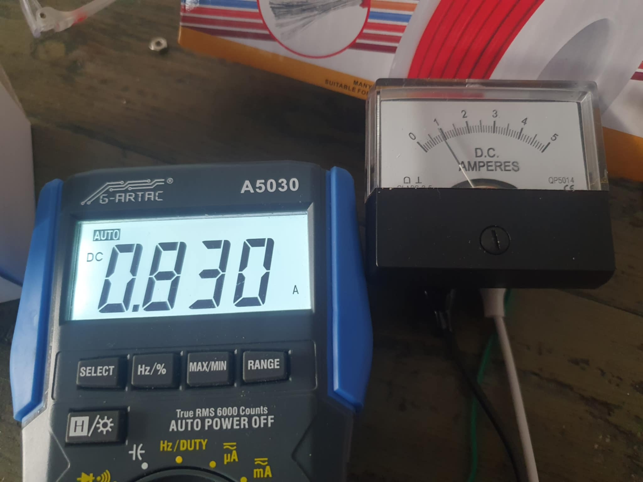
Looks like there is an internal shunt.
Still this thread taught me a bit about how shunts work.
To summarise, the reasons shunts work is because we are talking REALLY REALLY low, lower than the meter itself, but never-the-less well calculated, amount of resistance.
Honestly I love this hobby but just once I’d love a project with no curve balls.
Thanks all as usual.
Pix.
4 Likes
Hi Pix
Good luck with that. Mostly written around Charlie’s Law where Charlie thinks Murphy is a super optimist.
Cheers Bob
2 Likes
Pixmusix,
hello. Your direct reading ammeter has the range 0- 5A and would not normally require a shunt. The 0 - 50mV from the shunt would suit if you were looking and reading the signal via ADC. If you really need a shunt any time due to a high primary current say 100A then you would need to purchase a voltmeter with movement to suit the shunt voltage but with the scale marked for the DC current range. See example below.
Hoyt 2018 DC Ammeter with a DC moving coil, 1.5", 0 to 50 MV DC…
all the best,
Bryan
2 Likes
Jumping in late as usual. A moving coil meter is deflected by current. The actual mechanism is somewhat similar to a loudspeaker, with wires in a magnetic field. Pass a current through the wires creates a force. In a loudspeaker that pushes the diaphragm which moves air. In a meter, the force is resisted by a spring. The further the needle is deflected, the harder the spring pushes back.
Most meters are designed to fully deflect with not much current, typically 50µA to 1mA. Also, the wires used are very thin and have a significant resistance, often by design. For instance a 50µA meter could have a resistance of 1000Ω. Using the V=IR formula the voltage required to create a current of 50µA can be worked out - 50mV.
If the use of the meter is to measure voltage, then the 0->50µA is derived from the 0-? voltage. If the desired range is 0-100V then the meter requires a series resistor to limit the current to 0-50µA. The total resistance needs to be 2MΩ, so taking account of the meter resistance of 1000Ω, a series resistor of 1.999MΩ is required. This is often quoted as a resistance per V - in this case 20,000Ω per V. If the meter had full deflection with 1mA then that’s 1000Ω per V. When measuring, it pays to keep the introduced changes due to measuring to a minimum, so measuring voltage with a 20,000Ω per V meter is preferable to a 1000Ω per V meter. And the fact the meter has a high resistance internally is not significant.
Using the meter to measure current is a different matter. The lower limit is set by the meter itself. You can measure 20µA with a full scale of 50µA or a full scale of 1mA, but the very small deflection on a 1mA meter is almost unnoticable. But if the current to be measured is large, it pays to introduce as little resistance in the path as practical. A meter with full deflection at 1mA requires less turns of wire than the 50µA meter, so has a lower resistance (the force is proportional to current x number of turns). Its resistance might be 10Ω. For full deflection, only 10mV is required. This then allows the calculation of the total resistance needed to measure a particular current. For example 0->25A rearranging V=IR yields R=V/I - 10mV/25A = 0.01/25 or 0.0004Ω. The meter needs a parallel resistor so the total resistance is 0.0004Ω. One could go to the trouble of using the parallel resistor calculator but it is going to be so close to 0.0004Ω it doesn’t matter (error less than 0.1% which is likely much better than the meter itself).
So, by measuring the resistance of an unknown meter and its full scale deflection, one can calculate suitable series or parallel resistor to measure any voltage or current. This is easy to do with a digital multimeter, measure the resistance directly (the current used by a digital multimeter is unlikely to burn out the wires). Then introduce a current from a measured voltage source (AA battery is OK starting with a high resistance of say 50kΩ and reduce it until getting a significant deflection).
This works fine unless the meter already has internal added resistors, in which case they will interfere with the measurements (might be able to bridge them out with a jumper wire).
3 Likes
Allan,
An excellent text book presentation, good work.
Bryan
2 Likes