I’m building a simple voltage regulator with an in built meter.
It’s this amp meter and I’ve bought it’s matching shunt .
Sadly the shunt is too big for the box I want to house all this in.
HOWEVER, it would fit if I could remove that black plastic bar it’s sitting on.
I removed the plastic bar and there is nothing special about it and this has left me with questions marks about how this shunt is meant to work. 
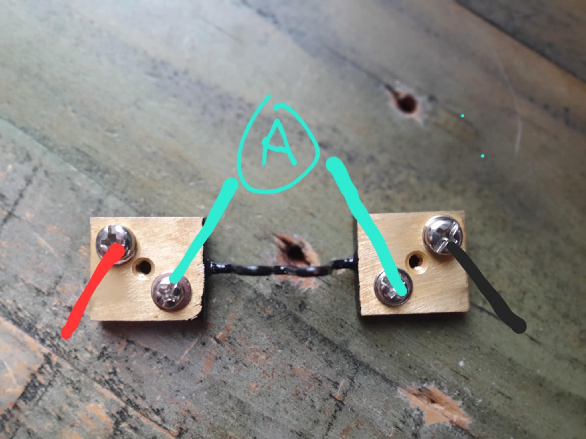
I think I get the purpose of the shunt.
Most of the current flows away from my amp meter leaving a small trickle for my meter to read.
As I understand it from online diagrams and videos I’m supposed to wire it up like this.
Intuitively it seems to me that the electricity will be impartial to the wiggly metal bar and the stranded copper 22awg wires to my amp meter (shown above in green). So, I had assumed that there was something in the plastic housing, like a resistor, that guided most of the current away form my amp meter. 
Now that I’ve removed the plastic base to have a look, I can see that this is literally just two bricks and a big chunky conductor between them so I am very confused how this works. What about my intuitions is wrong. Why wouldn’t all the current, or even just half the current, choose to flow through my meter instead of the chucky resistive wire between the two bricks?
edit: changed words for clarity
1 Like
My guess is that the plastic-covered bar is the shunt. A shunt will be a very low resistance component with capability to carry a high current without heating and changing its resistance. A bar of some type would be suitable because it could be easily trimmed to a suitable length and then accurately mounted between calibrated points. Your black plastic thing seems to fit that description.
Most of the current will flow through the shunt, and the device you have marked A is a volt meter that measure the voltage drop across the shunt. The meter is an analog computer that uses voltage and resistance to calculate current. The resistance it uses is a constant and should be marked on the dial (it must match the resistance of the shunt), the voltage is what the meter reads, and the result is the number that the needle points to.
I don’t think it will work without that bar!
Edit/ We might be talking about different things. The ‘bar’ that I am referring to is the plastic-covered piece running between the terminals. I think your image might show how it was after you have removed some form of mounting for the shunt. If that’s the case whatever you have already removed plays no part in the working of the shunt. /Edit
1 Like
Thanks for diving in @Jeff105671 
Yeah I think there might be some confusion for sure.
The link I posted shows the complete piece.
However, just for additional clarity let me post so additional photos of the one I bought.
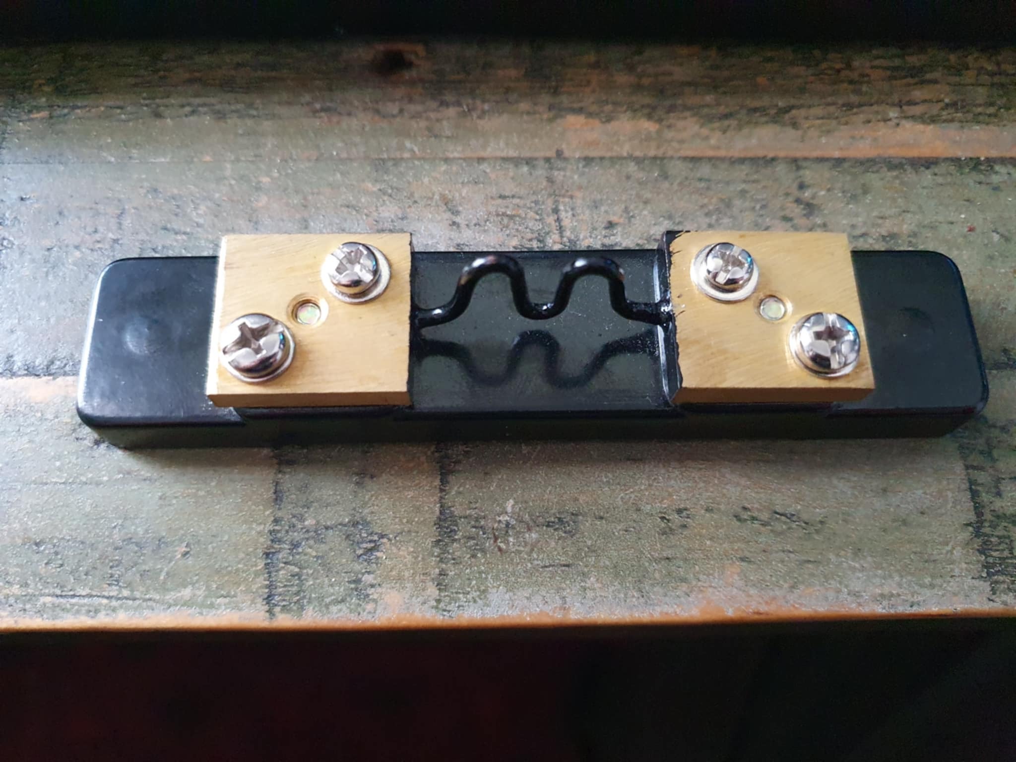
Here is a picture of the piece constructed.
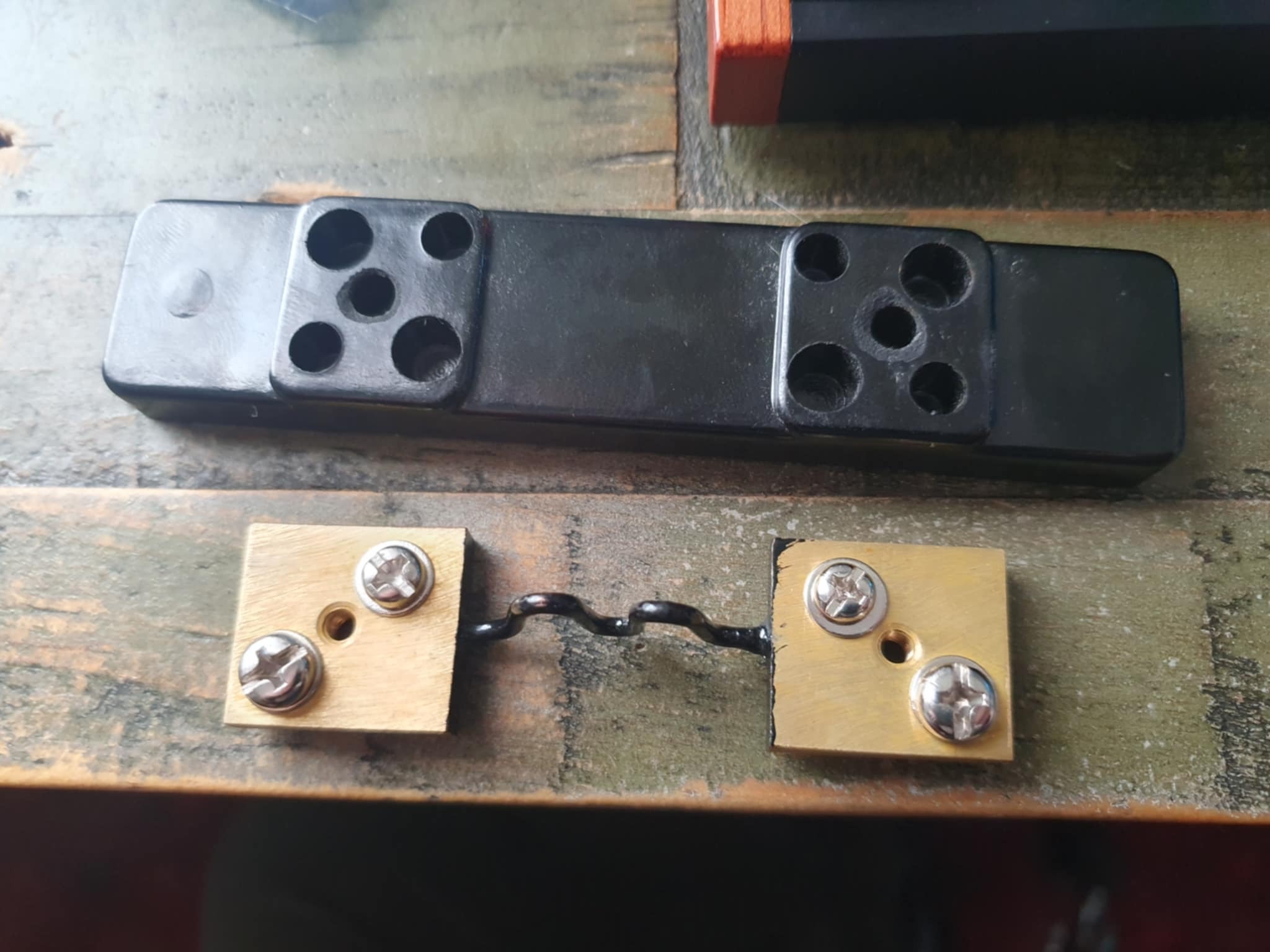
Here is a picture of it deconstructed.
The plastic bar I’m talking to is on the above.
Now I’m confused what plastic you were referring to?
Did you mean the squiggly isolated solid wire connecting the bricks?
1 Like
I thought all moving coil meters measure current? (although sometimes they label as volts). Mine is a 5a meter.
1 Like
OK. I have taken your ‘plastic bar’ as referring to the wiggly bit covered in plastic (which actually looked like a bar, not a wire, in the small image), and your reference to the base as something entirely different. While a bar or strap is commonly used as a shunt, in this case they have used some heavy wire.
Removing that base will have no effect on the operation of the shunt - the wiggly thing is the important bit. The only possible thing to consider is that the alignment of the shunt wire should probably stay more or less similar to how it was when the base was in place - they have presumably positioned it with some consideration to the airflow. Resistance will change with heating and alter the accuracy.
2 Likes
I have always regarded a moving coil meter as a voltmeter. I think that’s what most of the literature would call it.
However, voltage and current are always closely related, and given that the coil of the meter is a fixed resistance then it is probably a moot point as to what is being measured - the voltage applied to the meter, or the current that results from that applied voltage given the coil resistance.
It’s just the label on the dial that tells you what the number is referring to.
The important point is that a moving coil meter as used in an ammeter will not measure the current in the circuit directly - it will do it via a shunt. And to see how that happens it is easier to see the meter as measuring the voltage that is dropped across the shunt, rather than trying to figure out what proportion of the current is flowing through the meter and what proportion flows through the shunt. But it is all unambiguously related thanks to Ohms law, so you can consider it from multiple viewpoints.
1 Like
There are various versions of moving coil meters, make sure you use the right one.
I don’t think the meter you have linked is meant to used with the shunt you have linked.
It would put 0.01Ω in parallel with 0.01Ω.
Meter full scale 5A x 0.01Ω = 50mV. You probably wont need the shunt.
The shunt spec says 10mΩ resistance (0.01Ω) and 50mV drop at max current. The shunt documentation mentions a digital panel meter in range 0 to 200mV range. Then it talks about 0 to 200uv range. Then says 50mV drop equates to 5A. Often Jaycar documentation is not very good.
To use the shunt you would connect a volt meter across it that has a FSD of 50mV at 5A.
Don’t know if this makes it any clearer, experiment with the parts would be my path forward. I might have misunderstood this completely.
Regards
Jim
2 Likes
I am putting potentially 5a through this meter. My understanding is that analogue meters are designed to operate at milliamps not amps. Have I found the exception to the rule? Maybe these modern meters have inbuilt protection against high amps?
It could be that the guy who sold me the shunt himself didn’t really know what he was doing?
Edit:
Actually, on my shunt one terminal has 5a written on it and the other has 50mv. So that actually rhymes with the math you presented. I’ll assume the shunt is required for now.
Hi Pix
That “wriggly metal bar” is the shunt resistor and will be a small fraction of an ohm. The plastic is just a base to mount it on.
A moving coil meter is basically a CURRENT meter and should be marked on the scale "FSD (Full Scale Deflection) XXmA or µA which is the current required for full scale deflection of the pointer as the term implies.
This is made into a voltmeter by using a SERIES resistor and the current is increased by using a PARALLEL resistor as in your case.
The idea here is to “shunt” most of the current past the meter just leaving enough to operate the meter movement. Confusion behind this arises by marking the shunt in mV per Amp or if the shunt is rated 100A it could be mV per 100A.
So if the shunt is say 50A and the meter 1mA FSD the shunt would pass 49,999mA and the meter 1mA for a full scale reading and the voltage drop would be XXmV as marked.
All very confusing I know but if you do the logical thing and draw the equivalent circuit on a piece of paper it might make some sense.
Cheers Bob
2 Likes
My understanding is the meter linked would have a 0.01Ω shunt in it from which the moving coil would get its deflection. I think I remember discovering this when I pulled on old meter apart many years ago. Any analog moving coil meter, generally, has 50mV FSD so the coil itself cannot handle amps and would burn out.
The spec for the Jaycar volt meter has a 30k resistance.
I follow that. This brings me back to my original question.
If the shunt is low ohms, and the stranded copper wire I’m using to connect my 5a meter to the terminals is low ohms, why does most of the current prefer to travel through the shunt? Both paths are essentially shorts and the meter only has a resistance of 0.01 ohms.
Current follows the least path of resistance. 0.01Ω is very very small.
A length of copper wire could have more than this amount of resistance.
I just measured an alligator jumper, 0.5Ω. The multimeter leads alone measure 0.2Ω. A 30cm length of wire 0.2Ω.
In an ideal world the 0.01Ω meter in parallel with the 0.01Ω shunt; half should flow through each. But as you have some wires connecting the meter to the shunt the meter plus wire is probably much higher than wanted.
1 Like
Hi Pix
The meter movement itself will be much higher than this. Typically a imA FSD movement would be 100Ω. The Jaycar specs are confusing to say the least. They quote the meter and shunt both being 0.01Ω where I think they might mean the combination with the meter and shunt connected normally would be 0.01Ω so if this is correct most of the current would pass through the shunt.
You would do well to confirm this with Jaycar before you connect anything.
I do note that the meter FSD is not marked on the scale. You could measure this but if you don’t know how I am not going to describe the method as if you stuff it up the meter coil could become a fuse and provide the smoke to go with it. It is not complicated and a bit of research should turn up some diagrams. Good learning curve for you too.
Cheers Bob
PS Don’t just connect a DMM to measure the meter resistance or you probably will have smoke.
2 Likes
Hi James
To measure this value reliably you would need an ohmmeter using a 4 wire system.
In fact in operation the resistance of the connecting wires do not come into the equation as you are measuring across the shunt. Not including the wires. It is all the same current in the long run. As Mr kirschoff says the addition of all the currents into and out of a junction must be zero.
Cheers Bob
1 Like
Understand.
My point to Pix is that the wire connecting the amp meter to the shunt can have an effect; at such low resistance levels and cannot be ignored. In my opinion most current flows through the shunt because of these wires, even though both have the same resistance.
Jaycar has a number of amp meters and one voltage meter. The amp meters have various low resistance the voltage high resistance.
If I was doing this I would carefully determine the meter operation by vary voltage and hence current at very low levels ar first just to see any meter movement. These analog meters can be very easily damaged. From my experiments and knowledge I would probably find the meter is not what I think it is by how they describe it. Jaycar should have a diagram of how to connect the meters. Of course analog meters are not used much any more, digital much easier to connect and use.
Regards Jim
2 Likes
Man this is somehow more complicated that I thought.
I’ll throw the circuit I drew in my original post in series with a dimmed LED matrix and start with some low current. That way I can test the meter hopefully without breaking it.
James you might have nailed this.
I had a look at the box it came in and the barcode had MU45 written on it.
I found this article googling MU45 Datasheet.
The specs imply it has an internal shunt.
That seems amazing to me given how big the shunt I have is.
Doesnt feel like it would fit.
Have any of you ever heard of such a thing?
Yes.
As you can from the spec below, up to 5A can be internal; higher than that external as seen from the pic.
MU-45 Size: 58x52mm
DC 50μA, 100μA, 1mA, 50mA, 100mA, 200mA,500mA;
1A, 2A, 3A, 5A (with internal shunt for rating 1A ~ 5A);
10A, 15A, 20A, 30A,50A (With external Shunt for rating 10A ~ 50A)
All these meter movements are essentially current driven as @Robert93820 said. Using a shunt ensures the meter movement is not damaged. Voltage meters have a much higher input resistance due to the use of internal resistors to limit the meter movement current to meet the spec.
I have one that looks almost exactly the same, despite that it’s probably 50 years older and labelled MRA-45B rather than MU-45. The internal shunt is a length of think copper bar. No external shunt is required.
This is what it looks like. I had to take it apart because when I took it out to look at I saw that the hardware used for the case had rusted badly. I have no idea why because it wasn’t damp. Thankfully the meter is still fine.
2 Likes
Looks like the guy who sold me the shunt was misinformed.
I’ll try it without the shunt I suppose.