Hey @Luke202527,
I’ve just had a deep dive into this and I think you may be encountering an issue that is specific to older Arduino boards.
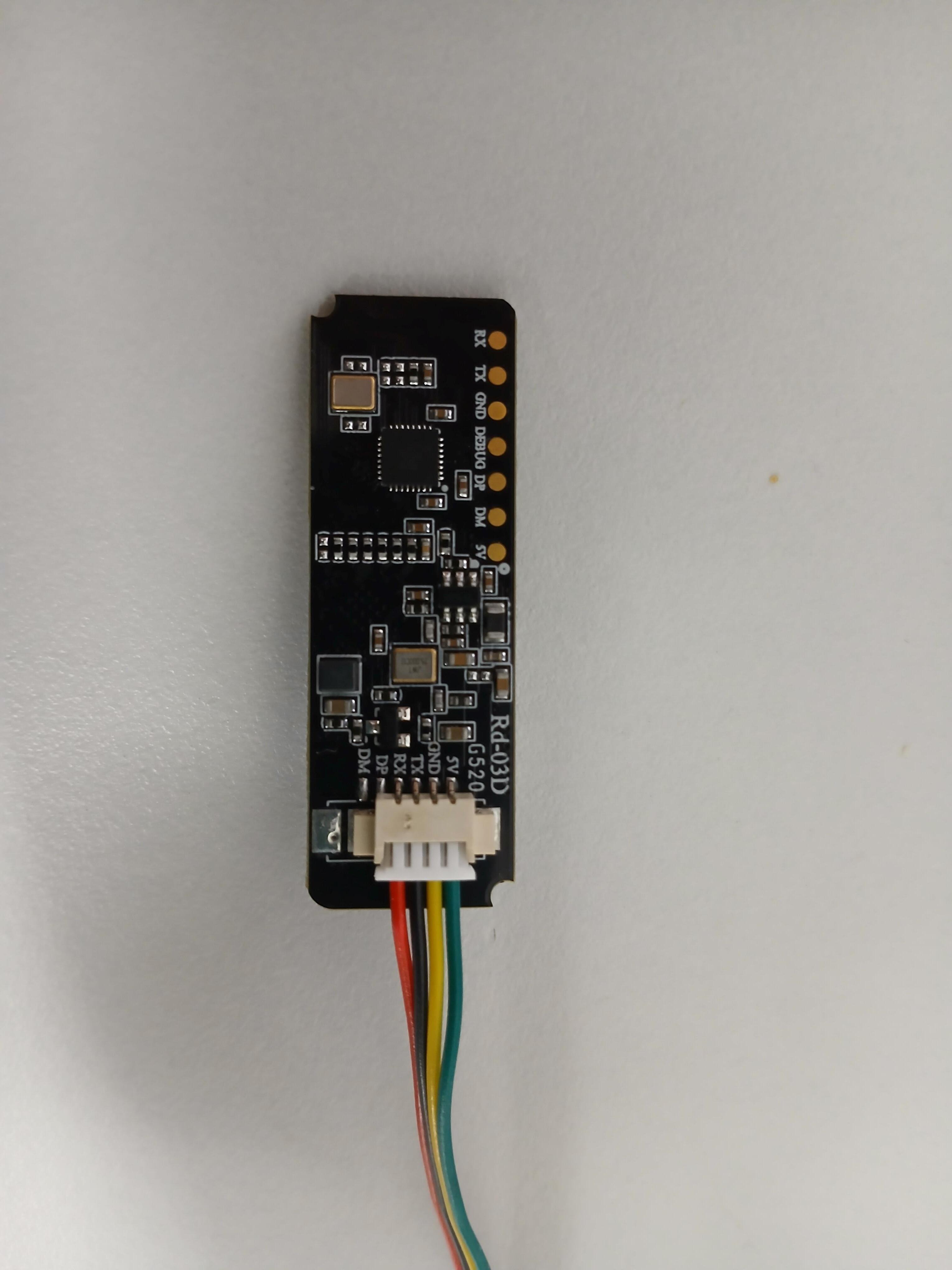
First of all, the G520 is not an issue; I get the same results with older and newer mmWave boards.
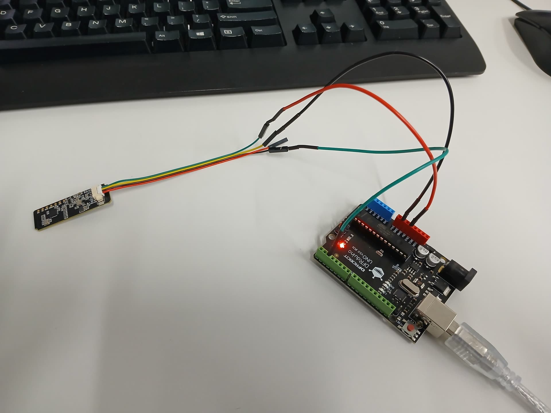
The wiring and code you have work fine when using an Arduino R4, and when I plugged in my R3, it also worked. When developing the code, I used this Uno R3 and was happy that this managed to work on it as well. However, I plugged in another R3 I had lying around, and I got the same issue as you. In fact, I got the same issue that @Nader297638 was having.
When I run this with the R4, a Raspberry Pi Pico and an ESP32 (some in C++, some in MicroPython), they read the start of the message and the end of the message as the following.
0xAA 0xFF … (middle part of message here) … 0x55 0xCC
But when I read it on one of my R3s I get the following message:
0xAD 0x01 … (middle part of message here) … 0x52 0x8C
And because the library is looking for the first set of values for the head and tail ends of these messages, it doesn’t register that it has read a valid output. So I went ahead and modified the library to look for the new header and tail, and it started reading. However, there seems to be some sort of bit shifting or corruption happening as not only are the header and tail different, but the distance, angle and speed values are as well. They read consistently, but they are all wrong. I tried to see if I could apply an offset (if it was consistently reading at an offset, we could calibrate it), but the shifting of the bits seems random.
Why is this happening? My probably something very weird hardware-wise. A baud rate of 256,000 is a very non-standard rate and exceptionally fast for software serial. The fact that I had an R3 that worked, and another that didn’t, I suspect there might be some timing issues that are only present on certain R3 boards. We are really getting caught on some out-of-the-blue nonsense here, unfortunately.
So the bottom line is that software serial can’t support this on older R3 boards. Some fixes for this are to instead use an R4 that supports reading at this rate through software serial, or using the actual hardware-based serial on the R3 that you have (through pins 0 and 1). The only issue is that the hardware serial on your board is the same serial that you use to send and receive data from your pc, so you won’t be able to send the output data to the serial monitor or processing IDE. You might need an OLED screen or something else to view that data. If you are applying this in a project, you might not need to view it on your pc at all, but it makes debugging difficult. @Nader297638 was able to get it going as the Mega has a 2nd UART channel to use (in addition to the USB one), the Uno R4 has a 2nd one as well.
If you do want to try out the hardware serial approach, I have altered the library to use it instead of software. If you follow the same process from the guide of installing a library, you should be able to overwrite the old one:
RD03D_Hardware_Serial.zip (1.4 KB)
#include <RadarSensor.h>

RadarSensor radar;

void setup() {
  radar.begin(256000); // Radar connected to pins 0 (RX) and 1 (TX)
  // You cannot use Serial.print anymore on Uno if the radar is connected here
}

void loop() {
  if(radar.update()) {
    RadarTarget tgt = radar.getTarget();
  }
}
Sorry about all this hassle, you seem to of been snagged on a very weird bug, I’ll also go ahead and update the guides to mention this issue as well.
Cheers!
-Jaryd